Quite a while ago now, I posted what I said would be my last post on this blog - at least for a while. I have, however, decided to add a one-off post explaining London Underground 2-aspect signalling. This will deal with the "legacy signalling" used on manually-driven lines only - and even then, I don't quite treat everything. There are one or two things I'm not completely sure about and, in these instances, I try to make that clear. Any corrections from anyone who knows more would obviously be very welcome.
I started writing this as a short, personal explanation for a friend of a single feature of LU signalling and it sort of ballooned a bit. Having written something quite long and - I hope - fairly comprehensive, I thought I should share it. So, here goes:
LU (London Underground) predominantly uses 2-aspect signalling on its manually-driven lines; although 3-aspect (and some 4-aspect) signalling is used on the outer extremities of the Metropolitan line. With 2-aspect signalling, you essentially have a 'go' and a 'stop' signal; while with "multi-aspect" signalling, additional aspects provide information about other signals still to come. Since multi-aspect signalling is confined to the Metropolitan line, I won't deal with that here, but we will have (lots) more on 2-aspect signalling shortly.
Now then, the purpose of signalling is to keep trains a safe distance apart - it is for spacing, essentially. The problem with trains is that they are very big and very heavy and so they take a long time to stop. They also cannot swerve to avoid obstacles. For this reason, it is not really possible for train drivers to keep their trains a safe distance apart simply by driving on 'line of sight.' The fact is that if you're driving a train and you come round a corner at full speed and see a train stopped ahead of you, you are going to hit that train.
So, to avoid collisions, we have signalling. On LU - as on most conventional railways - the track is divided up into discrete, fixed 'blocks' and entry into a block is controlled by fixed, lineside signals. This is called 'fixed block signalling.' The principle is that only one train may occupy a block at any given time. In this way, trains are kept a safe distance apart. If there is a train already in a block, an approaching train may not enter that block until it is clear. Once the train ahead has left the block, the next train may enter.
Obviously, this ensures that trains are kept safely apart, but the other nice things about signals are that they are easy to see, you can learn their rough location (drivers are expected to know this), you can provide repeaters for them and you can have multi-aspect signalling (where appropriate), which allows signals to give lots of advance warning of a need to stop. This makes stopping at signals relatively easy. By contrast, it would not be possible for a driver to reliably stop short of a train that had come to a stop ahead, unless they were travelling very slowly and had plenty of time in which to see it, for the reasons I mentioned above.
Spacing is not the only function of signals, though. Signalling also takes care of more complex things, like junctions, where you have to make sure trains go the right way and that certain trains are held so that other trains can cross their paths. You can equip signals with indications of the route that has been set for the train and you can use them to control the flow of traffic on the railway. In this latter case, they are similar to traffic lights on the road, although the analogy does not apply very well to the former cases.
2. The Basics
So, simple, standard LU signals show 2-aspects: a red (or 'danger') aspect and a green (or 'clear') aspect:
 |
| (a) A 2-aspect signal showing a red (or 'danger') aspect. This is signal JD10 at West Hampstead. I believe it used to be the station starter on the southbound road, but it is no longer in use. (This image is reproduced here by kind permission of the copyright holder - "Flickr" user "bowroaduk". © All rights reserved by "bowroaduk". "bowroaduk" is not affiliated in any way with this blog and has played no part in the production of this post. Their kind permission to use this image does not imply any endorsement of the content of this blog. This image has been cropped from the original image available here. Any requests to re-use this image must be addressed to "bowroaduk".) |
 | |
| (b) A 2-aspect signal showing a green (or 'clear') aspect. This is signal A204 at West Finchley. I believe it used to be the station starter on the northbound road, but it is no longer in use. (This image is reproduced here by kind permission of the copyright holder - "Flickr" user "bowroaduk". © All
rights reserved by "bowroaduk". This image has been cropped from the
original image available here.) Figure 1: LU 2-aspect signals "in the flesh." |
 |
| (a) A 2-aspect signal showing a red (or 'danger') aspect. Note the identification plate, which shows that this is signal A700. I will be using this in future examples. It is no longer in use, but is located between Wembley Park and Kingsbury on the northbound road. |
 | ||
| (b) The same 2-aspect signal showing a green (or 'clear') aspect. Figure 2: Schematic diagrams of LU 2-aspect signals - to cover both bases. |
So, let's look at how this works. (I know it's very simple, but it's nice to see it all laid out). I'm going to take as an example the signalling arrangement that used to be in place between Wembley Park and Kingsbury on the northbound Jubilee.
| (a) A700 is at danger because there is a train (Train 1) in the block ahead (i.e. there is a train between it and the next signal). |
| (b) Train 1 has now cleared the block between A700 and A702 and so A700 has cleared to green. Because Train 1 has now passed A702 and entered the block ahead of it, A702 is at danger. |
| (c) If we zoom out a bit to examine the whole section between Wembley Park and Kingsbury we see that 2-aspect signals are concerned only with the block ahead of them. A signal will be green as long as the next block is clear - whether the signal afterwards is green or red. Figure 3: A diagram showing an example signal sequence, demonstrating how 2-aspect signals work. Sadly you will probably have to click on the images to make them clear, I don't have much control over their size, unfortunately. |
3. Overlaps
These are the basics, although it is a slight simplification. In reality, an overlap is provided so that a signal will not clear to green until the train ahead is some way past the next signal. So in our example, A700 would not clear to green until Train 1 was some distance (depending on line speed) from A702.
Let's examine the reason for this. Suppose things were different and A700 cleared the moment Train 1 passed A702. Under these circumstances, if Train 1 happened to come to a halt because of a problem just past A702, A700 would clear. The next train would be cleared past A700 and up to A702 and there would be no margin for error at all - even a small overrun when braking for A702 would cause a collision. So, in reality, the blocks actually start and end slightly beyond the signals. So, the block which A700 protects is in fact roughly here:
 |
| Figure 4: A diagram showing a more accurate view of the arrangement of blocks and signals. |
Thus:
 |
| (a) Because part of Train 1 is still in the overlap, A700 is at danger, even though the train is past signal A702. |
 |
| (b) Only now that Train 1 has fully cleared the overlap has A700 cleared to green. Figure 5: A diagram demonstrating the relationship between blocks and signals. |
3.1 Trainstops and tripcocks
To go into a little more detail, all manually driven LU trains are fitted with tripcocks and all conventional signals are fitted with trainstops. A trainstop is an arm which is raised when the signal is at danger and lowered when it is clear:
 |
| Figure 6: A raised trainstop arm. (This image is courtesy of "Flickr" user Kurt Raschke and has been cropped from the original image available here. The license applying to the use of this image may be viewed here.) |
As a result, if a train should pass a signal at danger, the tripcock arm will hit the raised trainstop arm and the train will be tripped to a halt. If, however, a train passes a clear signal, the trainstop arm will be lowered and the tripcock arm will not hit it, so the train will carry on as normal.
The overlaps are calculated so that, theoretically, if a train should pass a signal at danger it will be tripped to a complete stop before it can possibly collide with another train. In reality, this hasn't always worked, but we can consider the theory by taking the example shown in Figure 5b. The overlap beyond signal A702 should ensure that if Train 1 were stopped were it is in the figure, and a second train passed A702 at danger, it would stop before reaching Train 1. There would, as I've said, be no such safety margin if A700 cleared immediately after a train passed A702. Consider Figure 5a again. If Train 1 were stopped where it is in the figure and A700 were clear, a second train could proceed as far as A702. If it then passed A702 at danger it would hit Train 1. This horrible scenario is prevented by the overlap, as shown in Figure 5a. Because of the overlap, if Train 1 were stopped where it is in the figure, there would be no danger of a collision, because a second train would be held at A700. If it passed A700 at danger there would be plenty of time for it to come to a complete stop after being tripped.
4. Repeaters
Now, obviously there is a potential problem. Without advance warning - especially in a bendy tunnel - you will not know that there is a red signal ahead until you're quite close to it. In some circumstances, there will not be enough time to stop from full line speed if the first indication you get of a red signal is when you can physically see the signal itself. This will be either because the signal is obscured in general (e.g. if it's around a bend, or if there's an obstacle, such as a bridge, in the way), or because its location makes it difficult to see in certain conditions (e.g. a train coming in the other direction may obstruct your view of some signals). Where there is a danger of this, repeaters are provided to give advance warning of the aspect which the next signal is displaying (although I believe not every repeater repeats the next signal - they may repeat one further along the line).
Repeaters may actually repeat the aspect of more than one signal, but let's just focus on repeaters that only apply to the next signal for now. If the next signal is green, the repeater will be green and if the next signal is red, the repeater will be yellow.
 |
| (a) A 2-aspect repeater showing a yellow aspect. This is signal R491, which is between Queen's Park and Kilburn Park on the southbound road. It repeats signal A491 and is indicating that A491 is at danger. (This image is reproduced here by kind permission of the copyright holder - "Flickr" user "bowroaduk". © All rights reserved by "bowroaduk". This image has been cropped from the original image available here.) |
 |
| (b) A 2-aspect repeater showing a green aspect. This is signal RWG13, which is between Putney Bridge and East Putney on the westbound road. It repeats signal WG13 and is indicating that WG13 is green. (This image is reproduced here by kind permission of the copyright holder - "Flickr" user "bowroaduk". © All
rights reserved by "bowroaduk". This image has been cropped from the
original image available here.) Figure 7: LU 2-aspect repeaters "in the flesh." |
 |
| (a) A 2-aspect repeater showing a yellow aspect. Note the identification plate, which shows that this is signal R700. R700 is the repeater for signal A700 and here it is indicating that A700 is at danger. |
 |
| (b) The same 2-aspect repeater showing a green aspect. Here, R700 is indicating that A700 is green. Figure 8: Schematic diagrams of LU 2-aspect repeaters - to cover both bases. |
Repeaters for automatic signals are given the same number as the signal they repeat (for obvious reasons - so that people know which signal(s) the repeater pertains to), except that the 'A' is replaced by an 'R'. Thus, signal R700 repeats A700. Repeaters for semi-automatic signals are identified by the exact number of the signal they repeat, prefixed with the letter 'R'. Thus, signal RWG13 repeats signal WG13.
Let's see this in action:
| (a) A700 is at danger because Train 1 is in the block ahead. Therefore R700 is showing a yellow aspect to warn drivers of the danger signal ahead. Since A702 is clear, R702 is also green. |
| (b) In this wider view we can see the complete sequence between Wembley Park and Kingsbury. Figure 9: A diagram showing an example signal sequence, demonstrating how 2-aspect repeaters work. |
4.1 Repeaters which repeat more than one signal
You may have noticed that one of the repeaters in my diagram was numbered R704AB. This signal repeats two signals - A704A and A704B. In this case, if either A704A or A704B is red (including if both are red), then R704AB will be yellow. R704AB will only be green if both of the signals it repeats are green:
| (a) When both A704A and A704B are clear, R704AB is green. Note also that R704A is also green, because A704A is green. |
| (b) Since Train 1 has passed A704A, it is at danger. R704A and R704AB are therefore yellow. Note that R704AB is yellow even though A704B is still green. |
| (c) Train 1 has now passed A704B (not shown) and A704A has cleared. Because A704A is clear, R704A is green. However, because A704B is at danger - even though A704A is clear - R704AB is yellow. |
| (d) Train 1 has now cleared the block protected by A704B (not shown) and A704B has cleared. Because A704B and A704A are clear, R704AB is green. Note also that because A704A is clear, R704A is green. Figure 10: A diagram showing an example signal sequence, demonstrating how a repeater which repeats more than one signal works. |
4.2 Signals which have more than one repeater
It is also possible for a single signal to have more than one repeater; more than one repeater is usually provided only on particularly long or bendy sections. This is quite simple really, the repeaters simply work together. Let's take an example between Southwark and London Bridge on the eastbound road:
| (a) When A154 is green, both R154/1 and R154/2 are green, for they both repeat the same signal. |
| (b) When A154 is red, both R154/1 and R154/2 are yellow, for they both repeat the same signal. Figure 11: A diagram showing an example signal sequence, demonstrating how two repeaters may be used to repeat the same signal. |
5. Fog Repeaters
In addition to all of this, there is a special type of repeater called the fog repeater; these work in exactly the same way as normal repeaters. They are not provided in tunnels, but many of the signals on the surface will have an associated fog repeater. These were originally only illuminated during foggy conditions and they were provided to give additional warning. It can be very hard to see the signals in thick fog and so drivers would have to drive very cautiously without the extra warning provided by fog repeaters. This would cripple the railway, as everything would have to slow down. Also, they are generally located 120 m before the signal they repeat, in order to give drivers a very clear idea of how far they are from a red signal. Nowadays fog repeaters are always illuminated to try and drive down the number of signals passed at danger. As we have seen, a signal passed at danger (or 'SPAD') is a very serious incident as it means that a train has entered a block which is already occupied by another train. In some even more severe cases it may mean that a train has proceeded into the path of another train - particularly at junctions - which can have horrendous consequences. It may also mean that a train has passed onto a set of points which are not set in its favour, which can result in derailment.
Fog repeaters look like this:
 |
| (a) A fog repeater showing a yellow aspect. This is signal FR556A, which is seen here at the old North Weald station. London Underground trains no longer serve North Weald; however, the Epping Ongar Railway still operates heritage runs over much of the old line on weekends and public holidays. This signal repeats A556A and is indicating that A556A is at danger. (This image is reproduced here by kind permission of the copyright holder - "Flickr" user Ian Robinson. © All rights reserved by Ian Robinson. Ian Robinson is not affiliated in any way with this blog and has played no part in the production of this post. Their kind permission to use this image does not imply any endorsement of the content of this blog. This image has been cropped from the original image available here. Any requests to re-use this image must be addressed to Ian Robinson.) |
 |
| (b) A fog repeater showing a green aspect. This is signal FRWR33B, which is located at South Ealing on the westbound fast. It repeats signal WR33B and is indicating that WR33B is clear. (This image is courtesy of "Flickr" user Luigi Rosa and has been cropped from the original image available here. The license applying to the use of this image may be viewed here.) Figure 12: LU fog repeaters "in the flesh." |
 |
| (a) A fog repeater showing a yellow aspect. This is signal FR700 and it repeats signal A700 (as you can see). It is indicating that A700 is at danger. |
 |
| (b) The same fog repeater showing a green aspect. Figure 13: Schematic diagrams of LU fog repeaters - to cover both bases. |
We can now consider all of the signals between Wembley Park and Kingsbury on the northbound to see some fog repeaters in action:
 |
| Figure 14: Because Train 1 is in the block ahead, A702 is at danger. As a result, FR702 and R702 are yellow. As all other signals are green, all other fog repeaters are green. |
6. Combined Signals and Repeaters
In some cases on LU it is possible for a signal and a repeater signal to occur together - either physically on the same post:
 |
| Figure 15: A combined stop signal (A592) and repeater (R590A), which I believe is located between Hammersmith and Ravenscourt Park on the westbound road. (This image is reproduced here by kind permission of the copyright holder - "Flickr" user "bowroaduk". © All rights reserved by "bowroaduk". This image has been cropped from the original image available here.) |
 |
| Figure 16: A stop signal (J1A) and repeater (RJ1B), which I believe are located between Camden Town and Euston on the southbound Bank branch. These signals are no longer in use. Note the difference in the size and style of tunnel signals. (This image is reproduced here by kind permission of the copyright holder - "Flickr" user "bowroaduk". © All rights reserved by "bowroaduk". This image has been cropped from the original image available here.) |
 |
| Figure 17: A stop signal (WR33A) and fog repeater (FRWR33B). These signals are located on the westbound fast platform at South Ealing. (This image is courtesy of "Flickr" user Luigi Rosa and has been cropped from the original image available here. The license applying to the use of this image may be viewed here.) |
 |
(a) A combined stop signal (A579) and repeater (R581) showing a single
red aspect. Note that the aspect of R581 is suppressed, because A579 is
at danger. A driver must stop at this signal, just like any other red
signal. This signal is the station starter at Stamford Brook's eastbound
platform 3, on the District line.
|
 |
(b) Here we have the same combined stop signal and repeater. This time, A579 is green, indicating that a train may pass this signal; however the repeater is yellow, which indicates that A581 is at danger. Hence, whilst the driver is cleared to proceed past this signal, they should interpret the repeater as usual and expect to find the next signal at danger.
|
 |
| (c) A combined stop signal (A592) and repeater (R590A), which I believe is located between Hammersmith and Ravenscourt Park on the westbound road. A592 is green, indicating that a train may pass this signal. R590A is also green, indicating that A590A is green. As such, a driver may proceed past this signal and should interpret the repeater as usual. (This image is reproduced here by kind permission of the copyright holder - "Flickr" user "bowroaduk". © All
rights reserved by "bowroaduk". This image has been cropped from the
original image available here.) Figure 18: LU combined stop signals and repeaters "in the flesh." |
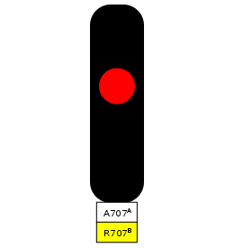 |
| (a) A combined stop signal (A707A) and repeater (R707B), showing a single red aspect. The aspect of R707B is suppressed because A707A is at danger. This signal is no longer in use, but it is located between Queensbury and Kingsbury on the southbound Jubilee line. |
 |
| (b) Here, A707A is green and a train may pass the signal, however R707B is yellow, indicating that A707B is at danger. |
 |
| (c) Here, both A707A and R707B are green. A train may pass the signal, which is informing the driver that A707B is also clear. Figure 19: Schematic diagrams of LU combined stop signals and repeaters - to cover both bases. |
| (a) A707A and A707B are clear and because A707B is green, R707B is also green. |
| (b) Train 1 has now passed A707A and so it is at danger. Because of this, the aspect of R707B is suppressed. It does not show a green aspect, even though A707B is green. If A707B were red, R707B would nevertheless still not show any aspect until A707A cleared. |
| (c) Train 1 has now passed A707B (not shown) and A707A has cleared. Because of this, the aspect of R707B is no longer suppressed. Instead, it shows a yellow aspect, repeating A707B as usual. |
| (d) Train 1 has now cleared the block protected by A707B (not shown) and A707B has cleared. Because of this, R707B is green, repeating A707B as usual. Figure 20: A diagram showing an example signal sequence, demonstrating how combined stop signals and repeaters work. |
6.1 Combined repeater and fog repeater
Sometimes a repeater and a fog repeater may occur together. Sometimes they will occur with a stop signal as well and sometimes they won't. The repeater and fog repeater may repeat exactly the same signals, making the fog repeater slightly redundant (remember they were originally intended for use only in foggy conditions). Sometimes, though, the repeater may repeat more signals than the fog repeater. There used to be an example of such a configuration between Upton Park and Plaistow on the westbound road; the area has now been resignalled following the introduction of the West Ham siding, however. Here, R912AB and FR912A used to occur together. It was therefore sometimes possible to have a yellow repeater occurring together with a green fog repeater. This would occur when A912B was at danger (meaning that R912AB would be yellow) and A912A was clear (meaning that FR912A would be green):
| Figure 21: In this case, A912B is at danger and so R912AB is yellow. However, A912A has cleared and so FR912A is green. As such, we have a yellow repeater (R912AB) occurring together with a green fog repeater (FR912A). |
7. Multi-Home Signalling
Throughout this piece so far, there's been an elephant in the room for me - and that's multi-home signalling. Where the signal number has a letter suffix (e.g. A704A), it usually indicates that the signal is one of multiple home signals. The first is suffixed with the letter 'A', the second with 'B' and so on. I believe it is most common to have 2 or 3 home signals, although you sometimes find 4 or 5. In LU parlance, a home signal is a signal before a platform, which protects a train in the platform from approaching trains.
Letter suffixes do not always indicate that a signal is one of multiple home signals, however. Also, London Underground signalling is a multifaceted beast and there are lots of exceptions, variants and special cases, so the description of multi-home signalling I am about to give does not necessarily always apply. One way of throwing a spanner in the works is to have a semi-auto signal at the end of the sequence. For example, let's return to the old sequence between Upton Park and Plaistow on the west. The home signals here used to be: A912A FR912B.FC1, A912B, FC1. N.B.: It is also perfectly possible, and not uncommon, for all of the home signals to be semi-auto, but these - I believe - work more or less like their automatic counterparts. Crossovers, sidings, junctions, etc. may occur outside a platform which has multi-home signalling - either before or after it - and are the reason for the use of semi-autos; in addition, they also affect the positioning of the blocks.
Anyway, with the caveat over, let's return to our general discussion of multi-home signalling. Now, platforms represent a significant chokepoint on LU, because trains generally have to stop at them. This means they have to start slowing down early, they must then stop and open up. Everybody needs to get on or off, then the train is closed up and it has to accelerate again. This all takes time and while it's happening, the next train is approaching. Platforms are also where delays are most likely to occur, because of passengers holding the doors open, handles down (people pulling the passenger emergency alarms, either at the station itself, or between stations (incidents are usually dealt with at stations)), luggage in the doors, overcrowding and many other factors. These can extend dwell times beyond those that were timetabled for. Naturally, any delays will have a knock-on effect and even a small delay of a minute or two can cause 'blocking back,' i.e. a traffic jam. This is because headways are quite small on London Underground - trains run very close together and so it's never long before the next train turns up. Also, on railways, overtaking is almost never an option and the trains take a relatively long time to start and stop and so even a small delay is amplified. Furthermore, with fixed block signalling, you can't get arbitrarily close to the train ahead, as you could on the road, you have to wait for the block to clear, before you can move.
One way of alleviating the problem is to reduce the overlap of the station starter (this is the signal at the end of a platform which clears trains to leave the station. All stations on LU's manually driven lines have starter signals, apart from Kensington (Olympia), Chesham and Croxley (southbound), to the best of my knowledge.
Imagine if the area around platforms were treated just like any other area and platforms were simply positioned in the midst of a block, as they sometimes are:
 |
| Figure 22: A diagram showing how the signalling arrangement around a station might look if normal, automatic signalling were employed. |
This is all very well, but applying the principle to the block protected by A107 requires us to have a large overlap after signal A109. This would be necessary to ensure that a train travelling at full line speed would not hit a train stopped beyond A109 if it SPADed A109. This is done, as we've seen, by not allowing A107 to clear until the next train is well past A109. The overlap then provides enough space for a train to be tripped to a halt if it should SPAD A109.
This, though, means that a train cannot be cleared past A107 and into the station until the next train is a long way past the starter. This is a waste of capacity, which can be alleviated by substantially shortening the overlap to just a few metres.
 |
| Figure 23: A diagram showing the short overlap of station starters. |
But there is an obvious problem. These overlaps are provided for safety reasons. Now, ordinarily, trains will stop at the station and so they will approach the station starter at low speed and will almost always be expected to stop short of the starter. Therefore long overlaps are not required as trains should not be approaching starter signals at full line speed, but will almost always be slowing down to stop at the station. As such, only a very short overlap is provided, but some overlap is still needed as a precaution.
Occasionally, however, stations may be closed. In these situations, a 5 mph speed limit is imposed as trains approach the starter. Trains are not expected to pass through the whole station at 5 mph, but most slow down to this speed before passing special 'station closed' boards. They may not resume line speed until beyond the starter. This is to compensate for the short overlap - it prevents trains from approaching the starter at full line speed and possibly going on to have a collision if they pass the starter at danger. It is also important to note that overlaps of some later signals may also have been calculated on the assumption that a train is approaching them after having stopped at the station (and, therefore, is not approaching at full line speed). For this latter reason, it is my understanding that in some locations on LU, starters are held at danger until a train has stopped (or almost stopped - this is presumably done by a timer). This is not done everywhere, although I believe it is common on the Bakerloo. Where it is done, it is done whether the station is open or closed and has the effect of always ensuring that a train leaves a station at low speed.
We can do better than this, however. Multi-home signalling allows a train to approach a station as the train ahead pulls out. This is achieved by a complex, finely tuned overlapping of the blocks. As a train pulls away from a station, it quickly clears the block protected by the outer home signal. The length and positioning of this block will have been calculated to ensure that the appropriate overlaps are present. When the departing train clears the block protected by the outer home signal, it obviously clears, allowing the next train to approach the station. The departing train will then clear the block protected by the next home signal and that signal will clear, allowing the approaching train to draw closer to the station. The process continues until the departing train has cleared the block protected by the inner home signal and the next train can enter the station.
This can all be understood more easily with a diagram:
 |
| (a) When Train 1 is in the station, you can see that it occupies the blocks protected by all three home signals and so all three are at danger. |
 |
| (b) As Train 1 pulls away, it quickly clears the block protected by A107A (the 'outer home' signal) and A107A clears. This would allow an approaching train to continue up to A107B. Of course the blocks will have been arranged such that an approaching train could not collide with Train 1 if it SPADed A107B- even if Train 1 stopped where it is in the figure. |
 |
| (c) Train 1 next clears the block protected by A107B and A107B clears. This would allow an approaching train to continue up to A107C. |
 |
| (d) Finally, Train 1 clears the block protected by A107C (the 'inner home' signal) and A107C clears. This would allow an approaching train to pull into the station. Note that the short overlap for signal A109 allows A107C to clear very quickly. Figure 24: A diagram demonstrating how multi-home signalling works. |
It is worth appreciating at this point, then, that the simple principles I began with (see, for example, Figure 3) are often just the foundations of more sophisticated, more intricate signalling techniques.
Also, I said above that multi-home signalling has been an elephant in the room. Recall previous instances where I have discussed multi-home signals, before I explained how they work. Take, for example, my caption to Figure 10c, where I explained "Train 1 has now passed A704B (not shown) and A704A has cleared." I had to be careful, because I didn't want to mislead, or confuse you. I can't be sure that these are indeed multi-home signals as there are many subtleties and the letter suffixes can simply be used - among other things - to allow signals to be inserted into the sequence (or removed from it) without destroying the logic of the numbering scheme. However, assuming that these signals are multi-home signals, if you look again at the whole sequence, you will realise that between step b and step c there will be a time when both A704A and A704B are at danger, while Train 1 is still in the platform. A704A will then clear as Train 1 makes its way out of the platform and A704B will remain at danger until Train 1 has completely cleared the platform and left the block that A704B protects. I was careful not to refer to the position of Train 1 and I hope it is now clear to you that Figure 10c represents the state of affairs where Train 1 has passed A704B and (because it is pulling out of the station and has cleared the block protected by A704A) A704A is clear.
It is, of course, worth noting that, because of the overlaps, it is common for there to be two danger signals in a row (see Figure 5a). However, multi-home signalling is unusual in that a train can be in more than one block at once. In Figure 5a, A702 is at danger not because Train 1 has entered the block protected by A702 (it has not yet done so), but purely because it is physically beyond A702, in the overlap, which will be detected.
8. Example
Before we move on to the more exciting and complex world of semi-automatic signals, I would just like to present you with a final example:
 |
| Figure 25: This is a part of the signalling arrangement that used to be in place between St. John's Wood and Baker Street on the southbound road. |
9. Introduction to Semi-Automatic Signals
You may have noticed that the last signal in the example - BM1 - is a semi-automatic signal. As I've said, semi-automatic signals can be operated by a signaller and only clear if the block ahead is clear and they are instructed to do so by a signaller, or by a machine. (It is possible that BM1 would clear quite late and that the first and last states represented on my diagram would be rare - particularly if the signal were being controlled by the machine - but it's not too important.) Automatic signals are green by default and go red when a train enters the block ahead. They are operated entirely by the passage of trains and will automatically clear when a train leaves the block which they protect. Semi-auto signals, by contrast, are red by default and must be explicitly commanded to turn green. Like automatic signals, they go red when a train passes them and enters the block ahead, but they will stay red until commanded to clear.
So what is the reason for this? Semi-autos are provided at complex locations such as junctions. Let's take Aldgate East junction as an example.
 |
| Figure 26: A diagram showing the signalling arrangements in the vicinity of Aldgate East junction. This diagram is based on an official signalling diagram and is schematic, like all of my diagrams. It cannot be assumed to accurately reflect the precise layout of the track. The aspects of the signals are intended to reflect a time when no train is present in the vicinity and no semi-automatic signals have been cleared. As such, only R852A, which repeats an automatic signal, is green. You may need to click on the image for a clearer view. Outside of Aldgate platform 1, past signal OB30, there is a short section of track leading to some buffer stops. This is a trap road. In the event that a train passes OB30 at danger, the train can be diverted onto the trap road and - if it fails to stop in time - into the buffers. This is considered preferable to allowing the train to continue onto Minories Junction and, perhaps, into the path of another train. N.B.: EB = eastbound, WB = westbound, NB = northbound, IR = inner rail, OR = outer rail. |
The next thing to consider is what happens if we approach Aldgate East from the other direction. Let's imagine a District line train is approaching Aldgate East from Tower Hill. We need to make sure that a train is held short of Aldgate East junction (OB38 is provided for the purpose) until it is its turn to proceed over the junction and into Aldgate East. The signal cannot clear and allow a train into Aldgate East simply because the block ahead is clear. A train may be due to cross Aldgate East junction to Liverpool Street on the westbound (OB45 would clear a train to do this) and/or one may be due to cross the junction on the eastbound from Liverpool Street (OB35 would clear a train to do this). As such, we need a system of interlocking to ensure that conflicting routes are not set. We can also use semi-auto signals to regulate and control the flow of traffic in accordance with the timetable, or the needs of the service.
This principle extends to the crossover to the east of Aldgate East station. Note that OB48 and OB44 are semi-auto signals. We could not have OB48 clear simply because there is no train in the block ahead. We need to make sure first that OB44 and OB48 do not both clear at the same time, second that either can clear (so long as the track ahead is clear) as required and, in general, that trains wait their turn.
There are a number of other semi-auto signals in the area. I imagine that OB47 and OB46 form part of a multi-home signalling arrangement, but I can't be sure. OB37, OB3700, OB34 and OB3400 are probably used for speed control (OB3700 and OB3400 are definitely speed control signals) - more on which later. It is again worth appreciating, then, that the reality of LU signalling is one of refinement and modification of the general principles I've been discussing. Some of these refinements may be quite esoteric and some may be holdovers from the past - the different LU lines have diverse, and often long, histories.
Another possible use of semi-auto signals is at locations where trains may run in both directions, for example, a train may pull into the westbound platform at Upney from Barking sidings, which are to the west:
 |
| Figure 27: A diagram showing the track layout around Upney. |
Finally, semi-auto signals are often used to stop trains before they reverse. They will be found, for instance, as the station starters at platforms where trains can reverse, as at Willesden Green until recently:
 |
| Figure 28: A diagram showing the track layout and signalling at Willesden Green. |
This also - in general - provides a handy way of holding trains to timetable and of regulating the service, by not allowing a train to proceed until the correct time, or until it is desirable. Again, drivers are usually contacted by radio by the line controller, but semi-automatic signals allow signallers to manage the flow of trains through their area, which is how it always used to be done. Indeed, it is common to have semi-automatic signals at the entrance and the exit (as well as in the middle) of "controlled areas" - i.e. areas under the direct control of a signal box or a control room, where sidings, crossovers, junctions and the like are found.
In summary, then, semi-automatic signals are used to coordinate the movements of trains through areas where trains may arrive from, and/or head onwards in, different directions.
As I have touched on, such control may be exercised by a human signaller, or by a machine. In the old days, controlled areas had signal boxes or signal cabins, where human signallers were based. It was the job of the signallers to set the appropriate route, as dictated by the timetable. When, however, things were not running smoothly, controllers could request that trains be 'short-turned' (reversed early, i.e. terminated short of their destination and sent back in the other direction) or 'stabled' (taken out of service and put away in a siding or depot). The signaller would have the job of setting the appropriate routes in this case.
Nowadays, apart from a few exceptions, even the manually driven lines are controlled from large, centralised control rooms. In general, the everyday working of trains through controlled areas is taken care of by machines, working on the basis of the timetable. The signallers, however, can take remote control, if, for example, a departure from the timetable is required (e.g. for short-turning or early stabling). Signallers also control extraordinary moves which may be required, correct mistakes, oversee and supervise the process, etc.
10. Junction Indicators
Many semi-automatic signals, such as OB40 (the station starter at Aldgate East on the eastbound), are simple, two-aspect signals, just like automatic signals. The only difference is the way they are operated, the signal itself looks the same and gives the same indications to a driver.
Some signals, such as OB45 (the station starter at Aldgate East on the westbound), are fitted with junction indicators. These are used at a diverging junction, where multiple routes can be set. They indicate to the driver which route is set and where, therefore, the train will go if it proceeds past the signal. It is very important that these are correctly observed. Partly, this is because a diverging route may have a lower speed limit, which will need to be obeyed; it is also important for ensuring that the train does not accept the wrong route and end up in the wrong place. For example, if a District line train is given the route to Liverpool Street at OB45 and accepts it, it will end up on the Hammersmith & City line. Not only is this no good for the passengers, or the service, but District line train operators (T/Ops) are not - I believe - road-trained over the Hammersmith & City line to Liverpool Street and would therefore find themselves on a section of track which they are not competent to drive on.
In some extreme examples, accepting a wrong route could turn out to be a real problem. For example, at Gunnersbury on the eastbound, it is possible to head straight on to South Acton on the London Overground, or to take the right hand route to Turnham Green on the District line. If a London Overground train accepted the wrong route here, it would find itself on a section of track which was not appropriately electrified and it would come to a halt - unable to proceed because it could not draw traction current. The track between Gunnersbury and Richmond is specially set up to enable both London Overground's Class 378s (which normally use a 'third rail' system with three rails) and the District line's D78s (which normally use a 'fourth rail' system with four rails) to operate. Beyond Gunnersbury, though, trains can only operate if they're on the correct line.1
A similar situation exists at Harrow-on-the-Hill. Platform 2 - which is usually used by the up Chiltern Railways service to London Marylebone - can be used by Metropolitan line trains; they cannot, however, continue southbound out of platform 2, they must return northbound along the fast to Moor Park. As the Chiltern line is not electrified, the conductor rails finish just outside platform 2. Not too long ago, a new Metropolitan line driver accepted the wrong route and continued out of platform 2 on the southbound. The train naturally came to a complete stop 'off juice' and couldn't move. I imagine it had to be towed back 'on juice.'
One final potential problem is exemplified at Hammersmith. If a District line train accepted the wrong route onto the eastbound Picc, after Barons Court it would descend into tube tunnels, which are much too short for it. To prevent a horrible accident, surface stock detectors are fitted before Barons Court. If a D stock train were to attempt to continue towards the tunnel, the top of it would hit three loops (naturally the shorter Piccadilly line trains pass under these). These were once filled with mercury, but I think something else is used now. If a train collides with these, it sets the next signal to danger and discharges traction current. The trainstop will bring a train to a halt if necessary, before it can hit the tunnel.
So, let's see some examples of junction indicators:
 |
| (a) A 2-aspect signal with junction indicator showing a red aspect. This is signal NQ17, which is no longer in use, but used to be the station starter at Finchley Central platform 2. Naturally, when red, it indicates that a train is not cleared past the signal. If it were showing a straight green aspect (with junction indicator not illuminated), it would indicate that the route to Mill Hill East is set. If it were showing a green aspect with harbour lights (the three white lights that make up the junction indicator) lit, it would indicate that the route to West Finchley is set. (This image is reproduced here by kind permission of the copyright holder - "Flickr" user "bowroaduk". © All rights reserved by "bowroaduk". This image has been cropped from the original image available here.) |
 |
| (b) Signal WD43, which has two junction indicators and is combined with the repeater RWD40A/1. This is the station starter at Barons Court westbound on the District line. As you can see, WD43 is showing a straight green aspect, with no junction indicators lit, indicating that the straight route to Hammersmith along the District line (technically the 'westbound local') is set. If this signal were showing a green aspect with the first (i.e. the one at 45°) junction indicator lit, it would indicate that the route to Hammersmith via the Piccadilly line (technically the 'westbound fast') was set. If it were showing a green aspect with the second (i.e. the one at 90°) junction indicator lit, it would indicate that the route to Hammersmith reversing siding is set. (This image is reproduced here by kind permission of the copyright holder - "Flickr" user "bowroaduk". © All rights reserved by "bowroaduk". This image has been cropped from the original image available here.) |
 | |
| (c) This is signal WM20.21. This is an old way of numbering signals with multiple routes. When the junction indicator is lit, this signal is WM20. When the junction indicator is not lit, this signal is WM21. One number for each route. This harks back to the old days - especially of semaphore signalling - when separate signals were used for each route. As you can see, here is an example of a 2-aspect signal with junction indicator lit (so it is WM20). This signal is located at Hanger Lane Junction, which is between Ealing Common and Ealing Broadway on the District and between Ealing Common and North Ealing on the Picc. With harbour lights illuminated like this, the signal is indicating that the route to Ealing Broadway is set. If the lights were not illuminated and the signal was showing a straight green, it would indicate that the route to North Ealing is set. (Image courtesy of the "District Dave" website.) Figure 29: LU signals with junction indicators "in the flesh." |
 |
| (a) Here we see a schematic view of signal NQ17, again at danger, indicating that a train is not cleared past the signal. |
 |
| (b) A view of the same signal showing a straight green aspect. As the harbour lights are not illuminated, this indicates that the route to Mill Hill East is set. |
 |
| (c) A view of the same signal showing a green aspect with harbour lights illuminated. This indicates that the route to West Finchley is set. Figure 30: Schematic diagrams of LU signals with junction indicators - to cover both bases. |
 |
| Figure 31: A view of Aldgate East junction showing a schematic view of how the station starter (OB45) indicates that the straight route to Tower Hill has been set. This is what a District line driver would expect to see. The signal is grossly oversized for clarity. |
 |
| Figure 32: A view of Aldgate East junction showing a schematic view of how the station starter (OB45) indicates that the right-hand route to Liverpool Street has been set. This is what a Hammersmith & City line driver would expect to see. |
 |
| Figure 33: A view of Hanger Lane junction showing a schematic view of how signal WM21 (see Figure 29c) indicates that the straight route to North Ealing has been set. This is what a Piccadilly line driver would expect to see. |
 |
| Figure 34: A view of Hanger Lane junction showing a schematic view of how signal WM20 indicates that the left-hand route to Ealing Broadway has been set. This is what a District line driver would expect to see. |
In most instances, the choice of which route is the 'straight route' is fairly obvious. It is not always like this, though. Let's return to signal NQ17. As I've stated before, a straight green aspect at this signal indicated that the route to Mill Hill East was set, even though getting onto the Mill Hill East branch requires a left turn:
 |
| (a) When signal NQ17 showed a straight green aspect, it indicated that the route to Mill Hill East had been set. The blue arrows show the actual route taken by a train, which initially requires a left turn. |
 |
| (b) When signal NQ17 showed a green aspect with harbour lights illuminated, it indicated that the route to West Finchley had been set. As before, the blue arrow indicates the route to the right which would be taken by a train. Figure 35: A view of Finchley Central showing a schematic view of how signal NQ17 indicated which route had been set. |
The second point is that route indicators are generally used to indicate the routes with lower permitted line speed and the normal route is usually the one with the highest permitted speed. Naturally this almost always means that the normal route is the straight(est) route. However, this is not always the case. Sometimes the route which is physically straight ahead has a lower permitted speed. In these cases, either the junction indicator will be used for the route which isn't straight - despite it having a higher permitted speed - or the route which isn't actually straight will nevertheless be the normal route and will be indicated by a straight green aspect.
All of this means that, whilst junction indicators essentially point you in the direction that you're going, route knowledge is often necessary to interpret a signal's indication accurately. Perhaps the best example of this is ED12, the wrong-road starter at High Street Kensington platform 2.
A wrong-road starter is a starter signal that clears trains to proceed 'wrong-road' (or 'bang road'). In LU jargon, 'wrong-road' moves are moves where a train proceeds against the normal direction of travel. So at High Street Kensington, platform 2 is ordinarily used for the eastbound District line and the outer rail Circle. However, the wrong-road starter clears trains back west - onto the inner rail Circle or the westbound District. Naturally a train will soon regain the correct side of the track, but for a short while, trains are travelling in the "wrong" direction. Please refer to Figure 26 if this is not clear. You can see here that Aldgate East's westbound platform 1 is usually used for westbound travel. However, the wrong-road starter OB41 clears trains eastbound from the westbound platform. A train would continue east for some time, before reaching the crossover and turning left, heading over it onto the eastbound main. OB44 is also a wrong-road signal (but not a starter signal) as it clears trains to travel west from the eastbound main onto the westbound main via the crossover.
A 'wrong-road,' or 'bang road' move can be one which is not signalled. For example, if a train needs to travel backwards, we say it is travelling 'wrong-road.' An example of this occurred during icy conditions a few years ago, when a train stalled on the eastbound Central line, approaching Greenford, and had to be driven back to Northolt 'wrong-road.' Until the crossover just outside Northolt, it was travelling westbound along the eastbound road.
'Wrong-road' is only used to refer to moves against the normal direction of travel. Where there is normal bi-directional running (e.g. on the Mill Hill East branch trains run in both directions), or where there is no single, normal direction of travel (e.g. sidings and bay roads (dead end platforms) do not count, as trains come in in one direction and go out in the other), we cannot designate moves as 'wrong-road.' Here, moves in both directions are perfectly normal. Of course, signalled wrong-road moves are also very routine, but there has to be an identifiable 'normal direction of travel' in order for there to be a contrasting 'wrong-road' move.
So anyway, back to ED12, the wrong-road starter at High Street platform 2:
 |
| Figure 36: Signal ED12, the wrong-road starter at High Street Kensington's platform 2. I believe this particular signal has actually been replaced with a more modern one, but the new one functions in exactly the same way. (Image courtesy of the "District Dave" website.) |
 |
| Figure 37: A diagram showing the route a train would take westbound to Earl's Court from High Street Kensington platform 2. You can see that the wrong-road starter ED12 is cleared with three white lights pointing right. Although the train does eventually turn right, it must first turn left in order to do so. |
A final point I feel I really ought to bring out is that junction indicators are only provided where there is a choice of routes. For example, if we return to OB41 - the wrong-road starter at Aldgate East's westbound platform 1 (see Figure 26) - we can see that it does not have a route indicator, even though a train cleared by this signal would make a left turn. Route indicators are only provided to distinguish between routes, not purely to indicate a turn.
10.1 Multiple junction indicators
As we saw in Figure 29b, a signal may have more than one junction indicator. In some instances one may point to the left and another to the right. A nice example is WP17, which is located on the westbound approach to Ealing Broadway, on the District line. Where WP17 clears with a straight green aspect, it indicates that the straight route into platform 8 is set. Where it clears with three white lights to the left, it indicates that the route into platform 7 is set and where it clears with three white lights to the right, it indicates that the route to platform 9 is set.
What about where there is more than one possible route to the right (or to the left, for that matter) - as in Figure 29b? The three white lights may be inclined at 45°, 90° and 135° to the vertical, on either side. Taking the example of right hand routes, the indicator inclined at the highest angle to the vertical indicates the most extreme route to the right. This usually means one of two things: either taking the first right of two, or going right and then right again. In some cases, you may actually take the second right of two and this may be the only right turn you make. The really important thing is that, ultimately, you finish in the rightmost place. Let's see this in action:
 |
| (a) A diagram of the track layout around High Street Kensington, showing - this time - signal ED23, which has two junction indicators. Here, ED23 is showing a straight green aspect, indicating that the straight route into platform 4 is set, as indicated by the blue arrow. No other signal except ED19 (and its repeater RED19, which is combined with ED23) is shown. |
 |
| (b) When ED23 clears with three white lights at 45°, it indicates that the route into platform 3 is set. Note that this route involves taking the second right. The train goes straight on at the first set of points, before turning right at the second set. |
 |
| (c) When ED23 clears with three white lights horizontally, it indicates that the route to ED19 and towards platform 2 is set. In this diagram, ED19 is clear, which would clear a train into platform 2. Note that this is the most extreme right - you can see that you are routed onto the tracks which are furthest to the right. You can also see that to get there, you must take the first right. Figure 38: Another view of High Street Kensington, showing a schematic view of how signal ED23 indicates which route has been set. |
 |
| (a) A diagram of the track layout around Barons Court and Hammersmith. The signal shown is WD43, which has two junction indicators and is combined with the repeater RWD40A/1. Here, WD43 is showing a straight green aspect, indicating that the straight route to Hammersmith platform 1, along the westbound 'local', is set (grey arrow). Naturally there are other signals along the route, but I haven't included these. Partly this is because I don't have access to the information and partly because it would be overkill, I think. |
 |
| (b) When WD43 clears with three white lights at 45°, it indicates that the route to Hammersmith platform 2, along the westbound 'fast', is set. Note that this route involves taking only one right. |
 |
| (c) When WD43 clears with three white lights horizontally, it indicates that the route into the siding is set. From there, I believe a train can be routed into Hammersmith platform 2 or platform 3. It would also be possible to route a train into Barons Court platform 3 (and perhaps platform 2, I can't be sure). Note that this is the most extreme right and that to get there you must go right and then right again. Figure 39: A view of the area between Barons Court and Hammersmith showing a schematic view of how signal WD43 indicates which route has been set. N.B.: 'local' is used to refer to track where trains stop at every station (or at least most of them), while on 'fast' tracks, some or all stations are missed out. If you look at the tube map, you can see that between Hammersmith and Acton Town, the Piccadilly line runs fast (stopping only at Turnham Green at certain times of day), while the District line serves all stations. Now, as you can tell, crossovers allow both types of train to run on both lines, so - to prevent confusion - we use the terms 'fast' and 'local.' As I say, the Piccadilly line usually runs along the fast - but can run along the local - while the District line is the other way round. Both Chiswick Park (both directions) and Stamford Brook (eastbound only) have no platforms on the fast lines, while at Turnham Green and Ravenscourt Park (and Stamford Brook westbound) platforms are provided on the fast lines. However, only Turnham Green's fast platforms see any kind of regular use; the rest are used only in extremis. If it is desired that a Piccadilly line train should stop at stations between Hammersmith and Acton Town (apart from Turnham Green, obviously), it is more likely that the train will be diverted down the local, rather than stop at the fast platforms. |
11. Repeaters at Junctions
In both Figures 38 and 39 there is a repeater combined with a signal with junction indicator. In Figure 38 you can see that the repeater (RED19) repeats a signal (ED19) which is only passed in the event that a particular route (that shown in Figure 38c) is set. If ED23 clears with a straight green, or with three white lights at 45°, the aspect of ED19 is irrelevant to the driver. Worse still, in both cases, the train is routed towards a dead-end platform. It is not desirable that the driver be shown a green repeater before a point at which the train must stop. So what happens if ED19 is clear for a Circle line train from Gloucester Road and ED23 is clear with the route set for platform 4, or platform 3? In the case of RED19, it will show a yellow aspect unless the route is set towards ED19, in which case it will accurately repeat ED19. As such, ED23 and RED19 will appear as they do in Figure 38a regardless of whether ED19 is red (as in the figure), or green.
The same principle is applied to RWD40A/1 in Figure 39. WD40A is the next stop signal along the westbound local and will only be passed when WD43 clears with a straight green, as in Figure 39a. In this case, RWD40A/1 accurately repeats WD40A, otherwise it always shows yellow.
It is also possible for the aspect of the repeater to be suppressed. In this case, the repeater will not show any aspect unless the route is cleared to the signal that the repeater repeats. So, for example, in Figure 38a, RED19 would show nothing if it worked in this way.
Sometimes, however, it is desirable to repeat the next signal for each available route. This is entirely possible and there are numerous locations where repeaters repeat one signal, or another (or another, depending on how many routes there are); but only one at a time, depending on which route is set. Such repeaters do not have to occur with stop signals - although they can. They may occur before the signal, or between the signal and a junction. Let's see an example:
 |
| (a) WL99 is clear with the straight route set to WL109. Consequently RWL109.89 repeats signal WL109. It is not repeating WL89. Since WL109 is red, RWL109.89 is yellow. |
 |
| (b) WL109 has now cleared, so RWL109.89 is green, even though WL89 is red. |
 |
| (c) Here WL99 is clear with the route set to WL89. Consequently RWL109.89 repeats signal WL89. It is not repeating WL109. Since WL89 is red, RWL109.89 is yellow. |
 |
| (d) WL89 has now cleared, so RWL109.89 is green. I believe that it is likely that RWL89 (the repeater after WL90) would remain yellow in this case, so as to avoid confusing a driver approaching WL90, but it is entirely possible that RWL89 would be green as well. Figure 40: Welcome to a small part of the immensely complex area of Acton Town. Just a few signals are shown - there are more in this area alone - with a view to demonstrating how repeaters at junctions can repeat different signals depending on which route is set. |
11.1 Repeaters with junction indicators
Repeaters (including fog repeaters) which repeat stop signals that have junction indicators may also have miniature junction indicators, to give advance warning of which route is set:
 |
| (a) This is signal WG150, which is located between Parsons Green and Putney Bridge on the westbound road. Combined with this signal is RWG15, the repeater of WG15 (visible in the background). At Putney Bridge there is a bay road, which saw fairly regular use, until recently. However, with the introduction of the S stock, none of the trains currently in use on the line can fit in the bay. It is set to be completely removed, but until then will only be able to hold engineers' trains and the like. When WG15 is clear with a straight green, it indicates that the route into the through platform - platform 3 - is set. Although nowadays unlikely to be seen, when WG15 clears with three white lights, it indicates that the route to the bay road is set. As you can see, RWG15 is equipped with a miniature junction indicator to forewarn the driver of the route that has been set. Here WG15 is at danger and so RWG15 is yellow. Naturally, the junction indicator is not lit. (Image courtesy of the "District Dave" website.) |
 |
| (b) Here, WG15 is showing a straight green aspect and hence RWG15 shows a straight green. This train is bound for platform 3. (Image courtesy of the "District Dave" website.) |
 |
| (c) This is signal EC6, the station starter at Earl's Court's eastbound platform 1. Combined with this is signal REC7, which - of course - repeats EC7. EC7 and REC7 (and, in fact, FREC7) have junction indicators. When EC7 is clear with a straight green, it indicates that the route to High Street Kensington is set and when it is clear with three white lights, it indicates that the route to Gloucester Road is set. You can see that REC7 is showing that EC7 is clear and that the route to Gloucester Road is set. (Image courtesy of the "District Dave" website.) Figure 41: LU repeaters with junction indicators "in the flesh." |
 |
| (a) This is the mildly complicated RWL25/29.25/16, which is showing a yellow aspect. This signal repeats WL25, which is located between Turnham Green and Acton Town on the westbound Piccadilly line (or rather the westbound fast). WL25 has a junction indicator and so, as you can see, does its repeater. When WL25 is clear with a straight green, it means that the route towards platform 2 (the westbound fast platform, which is generally served by the Piccadilly line) is set. The next signal in this case is WL29. When WL25 is clear with three white lights, it means that the route towards platform 1 (the westbound local platform, which is the preferred platform for District line trains) is set. The next signal in this case is WL16. So, obviously if WL25 is at danger, the signal in the diagram will be yellow. It will also be yellow if WL25 is clear with a straight green but WL29 is at danger and if WL25 is clear with three white lights but WL16 is at danger. This is because this signal also repeats WL29 or WL16, depending on which route is set. Naturally, when it is yellow, the junction indicator is not lit. |
 |
| (b) The same repeater showing a green aspect with junction indicator not lit. This means that WL25 is clear with a straight green and the route is set towards WL29, which is also clear. This means that the train has been routed towards platform 2. |
 |
| (c) Finally, we have the same repeater showing a green aspect with junction indicator lit. This means that WL25 is clear with three white lights and the route is set towards WL16, which is also clear. This means that the train has been routed towards platform 1. Figure 42: Schematic diagrams of LU repeaters with junction indicators - to cover both bases. |
How these work is pretty self-evident, but you can have a diagram anyway, because I'm nice like that:
 |
| (a) WL20 is red and so FRWL20 is yellow. |
 |
| (b) Here WL20 is clear with a straight green, which indicates that the straight route to South Ealing along the westbound local is set. District line trains would not take this route unless they were doing an empty stock move to Northfields depot, or something like that. As you can see, FRWL20 is also showing a straight green. |
 |
| (c) Finally we have WL20 clear with three white lights, which indicates that the route to Ealing Common is set. As you can see, FRWL20 is also showing a green with three white lights. Figure 43: Welcome to another part of the immensely complex area of Acton Town. This diagram demonstrates how repeaters with junction indicators work. |
12. Shunt Signals
In addition to all of this, there is a special type of signal that is also used - the shunt signal. Shunt signals are used to signal moves into and out of sidings, depots and other places where passengers shouldn't go. They are also commonly used for mainline shunt moves, which is where a train stops on the mainline, rather than in a siding, and reverses using a set of points. Let me show you an example:
 |
| Figure 44: A diagram demonstrating a mainline shunt move, using the example of Dagenham East. Trains may reverse 'east to west' at Dagenham East by using westbound platform 3 - the bay road. This is very simple - trains arrive from Dagenham Heathway on the eastbound and are cleared into the bay road by FG23B (which would clear with three white lights, of course.) This is the best option, because a train in the bay road is nicely out of the way and does not obstruct traffic on the eastbound or the westbound. When the time comes, a train can be cleared out of the bay road by FG8 and onto the westbound road towards Dagenham Heathway via both crossovers. You can see that trains can also reverse east to west off of platform 2, using the wrong-road starter FG5. Such a train would arrive as normal, being cleared by FG23B (which would clear with a straight green, of course) up to FG22, which clears trains into platform 2. Here the driver can change ends and then head back to Dagenham Heathway via the crossover. This is not such a good option as all the while a train is in platform 2, it is obstructing the eastbound road. As well as these moves, there is also a west to east move available - which is the one shown (in part) here - and it involves a mainline shunt. Trains would arrive in westbound platform 1 (cleared by FG2, of course) and then everybody would get off. The train would then carry on past FG4 and stop on the mainline at the limit of shunt (i.e. the point at which trains carrying out shunt moves stop.) This is marked by a small board with "Limit of Shunt" printed on it at Dagenham East, although white diamonds on black backgrounds are also used elsewhere (these are used as stopping marks in many places across London Underground). The train operator would then change ends. The limit of shunt is chosen such that the back of the train will be past ('in rear of') FG18. FG18 then clears the train up to FG22, which clears it into the eastbound platform, as shown by the blue arrows. FG18 can also clear a train into the bay road, which would generally only be of use if it were bound for the siding. This is the only way of reversing west to east, but - as you can see - it is much less convenient as trains must stop on the mainline. It also requires train operators to change ends by using the interconnecting doors, rather than a nice, handy platform and everybody has to get off. |
Now, as I've said, they are often used to clear trains to places where you don't want passengers to be and where passengers don't want to be - like sidings and depots. Moreover, the places that shunt signals clear trains to enter and leave are not usually signalled to the same high standard as running lines and some of the safety measures are often not in place.
As a result of this, it is generally not allowable to carry passengers over shunt moves. All passengers should leave a train before it proceeds past a shunt signal. In the event of a 'carry over,' where a passenger is unknowingly taken past a shunt signal, permission must be granted by the line controller before they can be taken back where they belong.
This is how it always used to be, but there're actually a few stories that surround this, too! Passengers never used to be allowed over shunt moves, but it's quite a hassle turfing everybody off. The history surrounding this is quite confusing, but as I understand it, there was a time when passengers were merely told to get off. This worked quite well in the days before iPods and automated announcements (which everybody tunes out anyway). That was until somebody tried to get off of a Central line train which was heading into Liverpool Street sidings. They were using the interconnecting doors, slipped and were killed. After that it was decided that trains would have to be tipped out by staff. Standard procedure is that the T/Op (train operator) checks the front two cars and closes the doors using special 'porter buttons,' which close all the doors in one car. A member of station staff does the rest. If there are two members of station staff to hand, they take half each. If there are none, the T/Op does the lot.
This is actually quite a good idea. I've been at Woodford countless times and seen people completely oblivious to the fact that the train was terminating. Another problem is people rushing onto the train when they see it arrive and not checking to see where it's going. On one memorable occasion I got off a Woodford via Hainault train and waited. It quickly became apparent that there was a man in car 1 who simply would not leave. He kept insisting that he wanted to go to London and, despite the T/Op's increasingly exasperated pleading, he would not budge. I thought at first maybe the man didn't have much English, but nope - he could understand, he just wasn't moving. Eventually it took a member of station staff to usher him off. Ultimately, he probably delayed his own journey to London by about three or four minutes.
Apart from the safety aspect, passengers who need to get into town do not want to spend 20 minutes in a siding - and it could be a lot longer if there is a problem on the line. As well as this, there have been instances of T/Ops being assaulted by angry passengers when they realised that the train was not going anywhere fast. I wouldn't want to be stuck on a train up a siding for twenty minutes with a furious drunk - would you?
Additionally, if a train is going to a depot, it may not be booked to re-enter service until the next day! Getting the train back to the station so that the punter can be deposited and then back to the depot would be a colossal nuisance. I remember reading one story by a driver ("tfc") who had taken a train into Stonebridge Park depot (at that time, Bakerloo line trains were not being detrained manually in the way I've described - instead three announcements were made). This unfortunate driver found "a drunk out cold, face down in his own vomit across a set of double doors." Upon informing the line controller, he was asked "Is he breathing driver?" In the end the man couldn't be awoken and the driver had to take the train all the way to Baker Street, where it was met by British Transport Police, who dealt with the matter. Obviously the train was now in the wrong place at the wrong time.
So we've had manual detrainment, in general, for a while, now. However, with the Olympics, it was decided - despite some considerable unhappiness about it - that the practice would be discontinued, because it takes time. The discontinuing was quite erratic and it seemed to vary with line. The Bakerloo line was one on which it was implemented, though, and for a while manual detrainment wasn't carried out. Then, one day, a kid was carried over into Queen's Park North Shed, where he used the interconnecting doors to slip off of the train and then headed along the tracks. Fortunately he was spotted by the T/Op, but after that Bakerloo line T/Ops refused to proceed into sidings and depots without detraining. Unfortunately, no staff were provided for the purpose, so for a few weeks the Bakerloo line constantly ran with minor delays. TfL informed us these were because of "operational issues."
Barriers have been fitted as a potential way around this but, in general, manual detrainment is still carried out; although whether it will last I can't say.
Anyway, back to signals. The traditional London Underground shunt signal consists of a white disk with a red stripe. The whole disk moves to indicate the aspect, like the old semaphore signalling. When the red stripe is horizontal, it indicates that the route is not clear and when it is at 45°, it indicates that the route is clear:
 |
| (a) A shunt signal which is not clear. This used to be signal WB31, although it has now, I believe, been replaced by a more modern equivalent. This signal was located at the end of eastbound platform 2 at West Kensington. When clear, this signal cleared trains into Lillie Bridge depot. (This image is reproduced here by kind permission of the copyright holder - "Flickr" user "bowroaduk". © All rights reserved by "bowroaduk". This image has been cropped from the original image available here.) |
 |
| (b) A shunt signal which is clear. This is signal WR7, which is located in Northfields depot. It is indicating that the train is cleared up to signal WR9, which is located at the end of number 6 road. WR9 is the 'outlet signal' and it clears trains out of the depot and into platforms 4, 3 and - I believe - 2. (This image is reproduced here by kind permission of the copyright holder - "Flickr" user "fish7373". © All
rights reserved by "fish7373". "fish7373" is not affiliated in any way
with this blog and has played no part in the production of this post.
Their kind permission to use this image does not imply any endorsement
of the content of this blog. This image has been cropped from the
original image available here. Any requests to re-use this image must be addressed to "fish7373".) Figure 45: Traditional LU shunt signals "in the flesh." |
 |
| (a) A shunt signal which is not clear. This is signal JE5, which you may remember from Figure 28. It is no longer in use, but it is located at the northern end of the southbound platform at Willesden Green. |
 |
| (b) The same shunt signal now clear. When clear like this, it indicated that the route into Willesden Green reversing siding was set. Figure 46: Schematic diagrams of traditional LU shunt signals - to cover both bases. |
 |
| (a) A fibre-optic shunt signal which is not clear. This is the new incarnation of signal ED169A. I believe it is located in the triangle sidings - between Earl's Court and High Street Kensington - at the end of number 36 road. I could be mistaken, though. When clear, it would clear a train out of the siding and up to ED230 and towards High Street Kensington. (This image is reproduced here by kind permission of the copyright holder - "Flickr" user Tom. © All rights reserved by Tom. Tom is not affiliated in any way with this blog and has played no part in the production of this post. Their kind permission to use this image does not imply any endorsement of the content of this blog. This image has been cropped from the original image available here. Any requests to re-use this image must be addressed to Tom.) |
 |
| (b) This is a fibre-optic shunt signal which is clear. This is signal WZ11, which is located at the end of platform 5 at Heathrow Terminal 5. It is indicating that the train is cleared into the number 1 siding to the west of the station. (This image is courtesy of "Flickr" user Tom Page and has been cropped from the original image available here. The license applying to the use of this image may be viewed here.) Figure 47:Fibre-optic shunt signals. |
 |
| (a) A London Underground 'position light shunt signal' which is not clear. This is signal 463, located in Neasden depot. (This image is reproduced here by kind permission of the copyright holder - "Flickr" user "bowroaduk". © All rights reserved by "bowroaduk". This image has been cropped from the original image available here.) |
 |
| (b) This is a position light shunt signal which is clear. This is signal WK 21, which is located at the end of platform 26 at Waterloo, on the Waterloo & City line. The Waterloo & City line uses a curious hybrid of Network Rail, traditional London Underground, and modern Central line signalling practices. I believe this shunt signal may well be a holdover from the days when the line was part of British Rail, but it doesn't matter, for a modern, LU position light shunt signal clears exactly like this. This signal is indicating that the train is cleared onto number 5 road in Waterloo depot. (This image is reproduced here by kind permission of the copyright holder - "Flickr" user "Mark Bowerbank". © All rights reserved by "Mark Bowerbank". "Mark Bowerbank" is not affiliated in any way with this blog and has played no part in the production of this post. Their kind permission to use this image does not imply any endorsement of the content of this blog. This image has been cropped from the original image available here. Any requests to re-use this image must be addressed to "Mark Bowerbank".) Figure 48: LU position light shunt signals "in the flesh." |
 |
| (a) A London Underground position light shunt signal which is not clear. Again I have chosen to use signal 463, as you can see. The small arrow on the identification plate is used to indicate which road the shunt signal applies to and is commonly found on shunt signals. This is one of the two possible ways a Network Rail position light shunt signal can indicate that it is not clear. |
 |
| (b) The same position light shunt signal which is now clear. This is how a Network Rail position light shunt signal would look if it were clear, too. |
 |
| (c) I have read that LU position light shunt signals could also clear like this. I would hazard a guess that the original signals worked in this way, but that now LU position light shunt signals clear in the way shown in Figure 49b. Network Rail position light shunt signals do not work in this way. As you can imagine, these signals can use simple bulbs, whereas the Network Rail style of signal has to use bi-colour LEDs (or, certainly, two sets of differently coloured LEDs in the lower right corner.) Although the alternative style of Network Rail signal gets around this problem by using a red light in the lower left hand corner and a white light in the lower right hand corner to indicate that it is not clear. |
 |
| (d) This is the alternative way for a Network Rail position light shunt signal to indicate that it is not clear. I include it here for completeness and because I believe this style of signal is still in use on the Waterloo & City line - although recall that that is something of an oddity. Figures (a) and (b) show current London Underground practices. Figure 49: Schematic diagrams of LU position light shunt signals - to cover both bases. |
 |
| Figure 50: We return to our old friend NQ17 and its associated shunt signal NQ47, both of which are no longer in use. As I've said before, NQ17 was the station starter at Finchley Central platform 2, while NQ47 was used to clear trains into the north siding. (This image is reproduced here by kind permission of the copyright holder - "Flickr" user "bowroaduk". © All rights reserved by "bowroaduk". This image has been cropped from the original image available here.) |
When shunt signals occur together with main signals, the two signals are separate - they control completely different routes. As such, only one signal may be clear at a time. The main signal must be red when the shunt signal clears and the shunt signal may not be clear when the main signal clears.
Because of this, fibre-optic shunt signals which occur alongside main signals generally only illuminate when they are clear. This is because there is no need for the shunt signal to be illuminated unless it is clear. It does not need to be lit up like ED169A in Figure 47a when the main signal is to be obeyed. It only needs to be lit up when it is clear (in this case, the main signal will still show danger). With the traditional rotating disk, the disk is always there, you cannot suppress it when it is not clear. However, with fibre-optic shunt signals you can avoid giving the driver two aspects unnecessarily.
Let's see this in action by returning to West Kensington's platform 2, where the old-style shunt signal has been replaced by a fibre-optic one:
 |
| (a) This is how signals WB34 and WB31 at West Kensington look now. WB34 is a standard 2-aspect signal (actually, it's converted from an older signal which had more aspects, but that doesn't matter), which clears trains on towards Earl's Court. WB31 is a fibre optic shunt signal which clears trains into Lillie Bridge depot. WB34 is at danger and you can see that WB31 is not illuminated because the route has not been cleared towards Lillie Bridge depot. WB31 will only illuminate when it is cleared, at all other times it is not illuminated. |
 |
| (b) Here WB34 is clear and so WB31 is not illuminated. The route is set towards Earl's Court, not Lillie Bridge depot, so WB31 isn't illuminated. |
 |
| (c) Finally WB31 is clear, indicating that the route has been set towards Lillie Bridge depot. As you can see, WB34 is at danger and is not suppressed. Nevertheless a train is cleared by the shunt signal, since these signals pertain to different routes. I can't be precisely sure of the logic, but I think it's easy to see why it's a good idea not to suppress WB34 and have it at danger. This ensures that trains slow down for the shunt move, which is likely to be undertaken at low speed. The shunt signal is also hard to see. Figure 51: Diagrams showing how fibre-optic shunt signals work alongside main signals. |
Where Network Rail position light shunt signals occur with main signals, they work like LU fibre-optic shunt signals. That is to say that they show nothing unless they are clear (when they show two white lights, as in Figure 49b). Their LU counterparts work in the same way.
12.1 Theatre route indicators
I've rather jumped the gun with this one (see Figures 44, 47b and 48b), but no matter. Just like main signals - which have junction indicators - many shunt signals need a way of indicating which of a number of possible routes has been set. Indeed, it is shunt signals which tend to be used at extremely complex locations. Even where a shunt signal controls only one route, the nature of the route may not be obvious without route knowledge. For example, if we return to Finchley Central, we can see that the route to the north siding is a little involved:
 |
| Figure 52: A diagram showing the actual route taken by a train cleared by NQ47 into the north siding. |
 |
| (a) Seen here is signal G4A, which occurs alongside G4B, as you can see. Both of these signals are now out of use, but they are located at Golders Green, at the southbound end of platform 4. G4B was the station starter and cleared trains on towards Hampstead. It is at danger. As you can see, G4A is also not clear and hence the theatre route indicator is not illuminated. Four routes could be set from G4A and each would have been displayed on the route indicator. I believe the first cleared trains to number 27 road, which is a shunting neck. Basically, a train proceeds onto 27 road and stops. The driver then changes ends and the train can head into Golders Green depot. The second route, I believe, was to 25 road (aka: number 2 siding), which is a siding located outside the station. The third route, I believe, was to 24 road (aka: number 1 siding), another siding, located alongside 25 road. The final route, I believe, was to the Golders Green loop, which basically acts like a siding, except it's connected at both ends. (This image is reproduced here by kind permission of the copyright holder - "Flickr" user "bowroaduk". © All rights reserved by "bowroaduk". This image has been cropped from the original image available here.) |
 |
| (b) This is signal WF4. As you can see, the signal is clear and the theatre route indicator is telling us that the third route from this signal is set. This is actually the third route of three available routes. This signal is located at the west end of platform 2 at Parsons Green (actually it's some way along the platform). Parsons Green is quite complicated and I will talk you through the area shortly. (This image is reproduced here by kind permission of the copyright holder - "Flickr" user "bowroaduk". © All
rights reserved by "bowroaduk". This image has been cropped from the
original image available here.) Figure 53: LU shunt signals with theatre route indicators "in the flesh." |
 |
| (a) We return to Dagenham East and FG18. Here, FG18 is not clear and so no route is shown on the route indicator. |
 |
| (b) Here, FG18 is clear. Two routes may be set from FG18, as described in the caption of Figure 44. Here, the first route is set, which is the route to the bay road. |
 |
| (c) Finally, we see FG18 clear with the second route set. This is the route up to FG22 and, from there, to eastbound platform 2. Figure 54: Schematic diagrams of LU shunt signals with theatre route indicators - to cover both bases. |
Despite this, as I have indicated, route knowledge is extremely important in correctly interpreting shunt signals. For example, shunt signal JL35 - which is no longer in use, but is located in Stanmore sidings - had twelve routes available from it, 1 for each of the 2 platforms3 and another ten for the ten sidings.
A particularly good example to demonstrate this point, though, is Parsons Green, which I'd like to talk you through (my thanks to "Colin", who provided almost all of this information; any mistakes, or omissions, though, will be mine):
 |
| Figure 55: In the words of the District line DVA (Digital Voice Announcer): This is Parsons Green. As you can see, Parsons Green is quite complicated, which means my diagram is a bit cluttered. I've done my best to make everything readable, but I'm sorry if it isn't perfectly clear. It shouldn't matter too much, though, I'll try and make sure my explanation compensates for the small, cluttered diagram. |
Now, let's turn our attention to the siding we passed along the way - 28 road. Signal WF130 is used to clear trains out of 28 road and up to WF3, which obviously clears them into platform 1. If a train is pulling out of 28 road, obviously the next train on the westbound has to be held at Fulham Broadway and cannot depart until at least when the train ex 28 road has cleared the overlap of WF3.
So far, so simple. As for going to 28 road, the signal which clears trains to do this is shunt signal WF26. As you can see, WF26 controls a wrong-road shunt move, as a train cleared by WF26 heads east along the westbound into 28 road. 28 road is the only possible destination from WF26, it is not possible to continue on to Fulham Broadway, the train can only go to the siding. Naturally, whilst this move is being carried out, the next train on the westbound must be held at Fulham Broadway and cannot be allowed to approach Parsons Green, since there is no signal in between. 28 road can take 1 train of D stock or S stock.
Now, back to westbound platform 1. Naturally, most of the time trains continue from platform 1 to Putney Bridge. WF2 is obviously the signal which clears trains to do this. The next stop signal after WF2 (not shown) is WGX660, but you can see that its repeater - RWGX660 - is shown on the diagram. It is also possible for a train on platform 1 to go into all of these four sidings: 21 road, 22 road, 23 road and 24 road. Signal WF9 is the signal which allows trains to do this and it displays '1' for the route to 21 road, '2' for the route to 22 road and so on. All four of these roads are long enough for one train and can take D stock or S stock.
Now: 21 road - 24 road. Let's go through in order. WF29 is the shunt signal which clears trains out of 21 road. There are three routes available from this signal. The first route allows trains to go to platform 2, the second allows trains to go to platform 1 and the third clears trains onto 29 road. As you can see, then, both platforms can be accessed from 21 road. However, trains do not enter service in platform 2 from 21 road, as not all of the train will be in the platform. Instead, the train must continue to Fulham Broadway to enter service.
As for 29 road, 29 road is very short. In the good old days, trains would shunt into 21 road and from there would be cleared to 29 road by WF29. To get out, they would be cleared by WF5 back into 21 road and from there they would be cleared to the appropriate platform by WF29. However, 29 road is too short for D stock and S stock and could only ever accommodate C stock. Since they've all gone, 29 road is now not generally in use (although doubtless engineers' trains can use it if required).
WF30 is the shunt signal for 22 road and has just 2 routes - 1 for platform 2, and 2 for platform 1 (remember what I said earlier about the first route always being the leftmost route, regardless of the platform numbering). Again, a train cannot enter service in platform 2 from 22 road, but must continue to Fulham Broadway.
23 road is just like 22 road (although you can enter service in platform 2 from 23 road). WF32 clears trains out of 23 road and there are two routes available - '1' for platform 2 and '2' for platform 1.
24 road, on the other hand, is like 21 road (again you can enter service in platform 2). WF33 is the signal which allows trains out of 24 road and it has three routes - the second is for platform 2 and the third is for platform 1. As for the first route, that is the route to 31 road, but 31 road is very, very short. It is not electrified and nothing but the smallest engineers' loco could use it. If ever a train does use it, WF8 would clear a train from 31 road onto 24 road. Access to and from 31 road is akin to access to and from 29 road.
Now for the eastbound road, where things get quite interesting. But before they do that, they will be boring. Now, a train approaching Parsons Green from Putney Bridge passes three signals (and some repeaters), the last of which is WF39 (not shown). Interestingly, beneath WF39 is WF37, an old-style calling on signal. It is no longer used, but it dates from the days when trains used to be coupled and uncoupled in service, so that longer trains could run in the peaks and carry more people. The calling on signal allows a train to proceed into an already occupied platform at low speed, in order that it can be coupled to the train that's already there.
Anyway, WF39 is obviously where a train would have to wait for trains leaving 21 - 24 roads and it also clears trains into platform 2. From here, the most simple and common thing a train can do is be cleared by WF38 up to A675 and on to Fulham Broadway (passing FR675 and R675 along the way, as you can see). It can also be cleared into the extra long siding to the left. Officially this is divided into 27 road and 25 road, though it is frequently referred to as '27 bottom' (27 road) and '27 top' (25 road). WF34 clears trains up to WF35, which clears them the rest of the way in. A train must pass both signals, whether it is to stop on 27 road or 25 road. If 27 road is vacant, a train will generally continue onto 27 road; however, obviously if it's occupied, then the next train has to stable on 25 road. Both 25 road and 27 road can take one train each and they can both take D stock or S stock.
WF10 clears a train on 27 road up to WF12, which clears trains from 25 road and 27 road up to WF4. Now, when a train reaches WF4, not all of the train is in the platform and so it must continue past WF4 and stop at the end of the platform. If a train is bound for platform 2, WF4 will be clear and will show the number '3', as in Figure 53b.
Now for the fun bit: platform 2. But before the fun fun bit, we need the boring fun bit. From platform 2 it is also possible to shunt back into 23 road and 24 road. This is done from signal WF6, which will show '1' for 23 road and '2' for 24 road. Hence it is also possible to shunt into 23 road and 24 road from 25 road and 27 road. First, a train from these roads will pass WF4 (displaying '3') and then it will pass WF6 (displaying '1' or '2', as appropriate).
It is also possible to access 21 road and 22 road, but this requires a fuss. Everybody must get off the train (except the T/Op, of course) and then the train will proceed past WF38 (which will be green) and stop at the limit of shunt (there is one stopping mark for the D stock and another for the S stock, since the S stock is longer). The train will then be in rear of WF4. The T/Op will then change ends and take the train past WF4 into 21 road (if WF4 is showing '1'), or 22 road (if WF4 is showing '2'). Naturally a train can also shunt into 21 road or 22 road from 25 road and 27 road, as well, using WF4.
So, to summarise:
| From | To | Via |
| Platform 1 | Putney Bridge | WF2, etc. |
| 21 road | WF9 (route '1') | |
| 22 road | WF9 (route '2') | |
| 23 road | WF9 (route '3') | |
| 24 road | WF9 (route '4') | |
| 28 road | WF26 | |
| Platform 2 | Fulham Broadway | WF38, A675, etc. |
| 27 road | WF34 and WF35 | |
| 25 road | WF34 and WF35 | |
| 23 road | WF6 (route '1') | |
| 24 road | WF6 (route '2') | |
| 21 road | WF38 to limit of shunt and then WF4 (route '1') | |
| 22 road | WF38 to limit of shunt and then WF4 (route '2') | |
| Fulham Broadway | Platform 1 | ...WF3 |
| Putney Bridge | Platform 2 | ...WF39 |
| 21 road | Platform 2 | WF29 (route '1') |
| Platform 1 | WF29 (route '2') | |
| 29 road | WF29 (route '3') | |
| 22 road | Platform 2 | WF30 (route '1') |
| Platform 1 | WF30 (route '2') | |
| 23 road | Platform 2 | WF32 (route '1') |
| Platform 1 | WF32 (route '2') | |
| 24 road | 31 road | WF33 (route '1') |
| Platform 2 | WF33 (route '2') | |
| Platform 1 | WF33 (route '3') | |
| 29 road | 21 road | WF5 |
| 31 road | 24 road | WF8 |
| 28 road | Platform 1 | WF130 and WF3 |
| 25 road | Platform 2 | WF12 and WF4 (route '3') |
| 22 road | WF12 and WF4 (route '2') | |
| 21 road | WF12 and WF4 (route '1') | |
| 27 road | Platform 2 | WF10, WF12 and WF4 (route '3') |
| 22 road | WF10, WF12 and WF4 (route '2') | |
| 21 road | WF10, WF12 and WF4 (route '1') |
Table 1: A table showing all of the locations one can get to from each location and the signals used for each move. Naturally, in some cases it is possible to go from one location to another and then to another. So, for example, all sidings can be accessed from all other sidings via the platforms. Thus, it is possible to go from 25 road to 23 road via platform 2. Rather than list all such moves, I've simply given you the route from 25 road to platform 2 and the route from platform 2 to 23 road. It would even be possible to get from 28 road to 27 road by going to platform 1, to 21/22/23/24 road, to platform 2 and to 27 road. It's very difficult to see why such a move would ever be carried out, though!
| Signal | Route | To |
| WF38 | - | A675 |
| A675 | - | Fulham Broadway |
| WF3 | - | Platform 1 |
| WF2 | - | WGX660 and towards Putney Bridge |
| WF33 | 1 | 31 road |
| 2 | Platform 2 | |
| 3 | Platform 1 | |
| WF32 | 1 | Platform 2 |
| 2 | Platform 1 | |
| WF8 | - | 24 road |
| WF30 | 1 | Platform 2 |
| 2 | Platform 1 | |
| WF29 | 1 | Platform 2 |
| 2 | Platform 1 | |
| 3 | 29 road | |
| WF5 | - | 21 road |
| WF6 | 1 | 23 road |
| 2 | 24 road | |
| WF4 | 1 | 21 road |
| 2 | 22 road | |
| 3 | WF6 | |
| WF9 | 1 | 21 road |
| 2 | 22 road | |
| 3 | 23 road | |
| 4 | 24 road | |
| WF34 | - | WF35 |
| WF35 | - | 25 road and 27 road |
| WF10 | - | WF12 |
| WF12 | - | WF4 |
| WF26 | - | 28 road |
| WF130 | - | Platform 1 |
Table 2: A table showing all of the routes available from each signal, giving either the final destination or the next signal.
13. Speed Control Signalling
The next thing I'd just like to give some small consideration to is speed control signalling. This is used at a number of locations - primarily junctions - where a SPAD could have horrific consequences; for example, a train might continue into the path of an oncoming train. The purpose of speed control signalling is to ensure that a train is going sufficiently slowly when approaching a signal that, in the event of a SPAD, it will be tripped to a halt long before it can come into harm's way.
As well as the safety aspect, this is good news for efficiency, too. What it means is that signals can be safely located quite close to junctions (and any other potentially dangerous locations). Without speed control, the signal controlling a junction (for example) would have to be far enough from it that a train travelling at full line speed could be tripped to a halt before reaching the junction, if it were to SPAD the signal. This would mean that the junction would be clear for a long time before the next train arrived, because the signal could not clear until the junction is clear and then the train would take a long time to reach the junction and travel over it, because it was held so far away. This is bad news for capacity. Speed control allows signals to be safely positioned closer to junctions, increasing capacity.
Let's see how it works by taking the example of Hanger Lane junction:
 |
| Figure 56: Hanger Lane junction and two signals - WM100 (plus RWM1) and WM1. As you can see, WM1 protects Hanger Lane junction. WM100 works alongside WM1 and is speed controlled. The numbering system for such signals is a little confusing. As I understand it, the same number is used for the speed controlled signal as the signal it works alongside, but one or two zeros are added to make a three digit number. Thus, WM1 becomes WM100. |
WM100 will not clear a train to continue on to WM1 until track-side equipment detects that the train is travelling at no more than 10 mph. Then, and only then, will signal WM100 clear to green. If a train SPADs WM1 at 10 mph or less, there is no risk of it reaching Hanger Lane Junction. This is speed control signalling.
In addition, there is also the repeater RWM1, which gives the driver of a train approaching WM1 additional warning.
As you can imagine, if WM1 is green, there is no need to impose the 10 mph speed limit and so, if WM1 is green, WM100 will also be green.
Let's have some diagrams!
 |
| (a) When signal WM1 is at danger, WM100 is also at danger. It remains at danger until an approaching train is travelling at no more than 10 mph. So, let's suppose that a train from Ealing Broadway is approaching and has yet to reduce its speed to below 10 mph; this is how the signals would be. This is also how they would be if no train were approaching at all. WM100 only clears to green when an approaching train has been verified as travelling at no more than 10 mph, or when WM1 clears to green. |
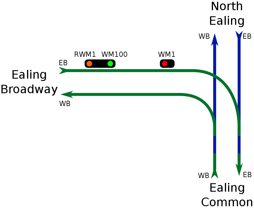 |
| (b) The approaching train (not shown) has now reduced its speed to <10 mph and so signal WM100 has cleared to green. In this example, WM1 is still at danger. |
 |
| (c) Eventually, WM1 will clear to green. If this happens before our train from Ealing Broadway passes WM100, this is how the signals will appear. Obviously it is also possible that WM1 could clear after the train has passed WM100. Since WM100 will return to red after just a few carriages pass the signal, in this case, WM1 will be green and WM100 red. Please note that the instant WM1 clears to green, WM100 will also clear (provided there is no train in the block ahead, of course!) and so the second step may be missed out altogether. This is also how the signals would be if WM1 had been cleared before a train had begun to approach, however fast it was travelling. Figure 57: A diagram showing an example signal sequence, demonstrating how speed control signalling works. |
 |
| Figure 58: A diagram showing the signalling arrangement at Elephant & Castle on the Bakerloo line. |
This works well, but what if there is a train departing from platform 4 using the crossover? Well, in this case, a train which SPADs BS21 at full line speed may fail to stop short of the crossover - resulting in a collision. We could move BS21 back, but that would waste capacity.
Instead, we have BS210, which is speed controlled. If a train SPADs BS210 at full line speed, it will be tripped to a halt short of the crossover. So, a train approaching Elephant & Castle will first encounter BS210, which will be held at danger until a suitable time delay has elapsed. After the time delay has elapsed, an approaching train will have slowed down sufficiently (if it has not, it will reach BS210 before it clears and will be tripped to a halt). BS210 can now clear the slow-moving train up to BS21. At this speed, if a train SPADs BS21 it will stop short of the crossover.
Naturally, if BS21 clears, BS210 will clear immediately.
Though I cannot be sure, I believe similar principles may be employed at some other locations to ensure compliance with speed restrictions. For example, say the speed limit drops from 40 mph to 20 mph - speed control signalling may be used to ensure that a train has reduced its speed appropriately. By holding a signal at danger until a train is travelling at 20 mph or less, the train is forced to obey the speed restriction. In addition, the red signal is a more prominent visual cue of a need to slow down than a small, grubby sign. I don't know too much about whether this is in use or not, however. It is important to underline how varied London Underground signalling is and how history has wreaked havoc on the Underground.
13.1 Draw up signals
And if you thought I was going to get any more certain, you were wrong. Draw up signals are odd things. They're basically a form of speed control peculiar to London Underground and they're generally found within platforms. They are used to protect short overlaps, for example at Baker Street. Almost immediately to the east of Baker Street station is Baker Street junction, which is where the Metropolitan line branches off:
 |
| Figure 59: A diagram showing the track layout around Baker Street. |
To avoid such a disaster, draw up signals are used. Much of this will sound familiar. If the station starter (MB17 at Baker Street) is at danger, its associated draw up signal (MB16/171 at Baker Street) will be at danger. As an eastbound Circle or Hammersmith & City line train approaches, a timer begins. After 4.5 s at Baker Street, the draw up signal clears to yellow. This 4.5 s should be enough to ensure that an approaching train is travelling slowly enough. Obviously, if the train passes MB16/171 before its 4.5 s are up, it will be tripped to a stop short of the junction.
Now the train can continue the rest of the way into the platform and stop. If it fails to stop, it will be tripped by the station starter and will be going sufficiently slowly that it will stop short of the junction.
As before, if MB17 clears, MB16/171 clears immediately.
Again, this is good news for safety, but it also means that we don't have to hold Circle and Hammersmith & City line trains outside of Baker Street while Metropolitan line trains are on the junction - which would throttle capacity. Draw up signals allow them to proceed into the station in complete safety.
Finally, draw up signals are installed in a limited number of other locations as a simple congestion easing measure. They allow trains to run closer together by allowing a train to continue at a reduced speed - in complete safety - before an overlap has been completely cleared.
Let's see some pictures. As I've said, they are strange beasts:
 |
| (a) A draw up signal showing a danger aspect. This is signal OE260 at Moorgate's westbound platform 2. It works alongside the station starter OE26 and protects trains departing platforms 3 & 4. The numbering of draw up signals is often (you may notice that there is an exception at Baker Street) the same as speed control signals for semi-auto draw up signals (most of them are semi-auto, I think) - you add one or two zeros, as required. You may have noticed that this is actually a converted four-aspect signal. (This image is reproduced here by kind permission of the copyright holder - "Flickr" user "bowroaduk". © All rights reserved by "bowroaduk". This image has been cropped from the original image available here.) |
 |
| (b) A draw up signal showing a yellow aspect. This is signal A8400 at Cannon Street and it's a funny thing. Notice that it's actually formed of two separate signal heads. Anyway, I don't know much about this signal, except that it's located on the westbound road. I think it may just be to ease congestion. As you can see, this one is automatic and so we've just added one zero to form its identification number, which has four digits. (This image is reproduced here by kind permission of the copyright holder - "Flickr" user "bowroaduk". © All rights reserved by "bowroaduk". This image has been cropped from the original image available here.) |
 |
| (c) A draw up signal showing a green aspect. This is signal EH900 at Embankment's eastbound Circle & District line platform. It works alongside the starter signal EH9 and protects a trailing crossover to the east of the station. Since EH900 is green, EH9 must be green. Figure 60: LU draw up signals "in the flesh." |
 |
| (a) A draw up signal showing a danger aspect. This is EC280, which is located in platform 3 at Earl's Court. Its purpose is to protect trains departing from platform 4 and crossing over onto the line from platform 3. Trains heading to West Kensington from platform 4 must cross over just outside platform 3. EC280 is red because EC28 is red. Either there is no train approaching EC280, or an approaching train has not yet reduced speed enough. |
 |
| (b) Here EC280 is yellow, meaning an approaching train has reduced speed sufficiently and can proceed the rest of the way into the platform and up to EC28. |
 |
| (c) Finally we have EC280 displaying a green aspect, which means that EC28 is green. Figure 61: Schematic diagrams of LU draw up signals - to cover both bases. |
 |
| Figure 62: This is A2250 at Farringdon eastbound. It is provided to relieve congestion, since this particular section of line has very short overlaps. As I've said, draw-up signals allow trains to safely run closer together, since they force a train to reduce its speed. As such, the longer distances that need to be maintained between trains running at full line speed can be reduced, since - at low speed - a train can be tripped to a halt in a very short distance. (This image is reproduced here by kind permission of the copyright holder - "Flickr" user "bowroaduk". © All rights reserved by "bowroaduk". This image has been cropped from the original image available here.) |
'Moorgate control' is a bit of a tangent, but while I'm here...
On 28th February 1975 a Northern City line train failed to stop at the terminus - Moorgate station - and collided with the buffers and then the tunnel wall. Due to the fairly large diameter of the tunnels, the front car was able to ride up over the buffers and the second car was forced underneath it - a phenomenon known as 'telescoping.' The cause of the incident was never satisfactorily determined, but it is known that the train did not slow down at all on its approach to the station and passed through at 30-40 mph; in fact, some passengers reported that the train sped up as it approached. Power had been applied to the motors until 2 seconds before the impact (although this does not necessarily indicate that it was accelerating) - all of which has made some people suspect the crash was a suicide. However, the coroner recorded a verdict of accidental death. The inquest found no evidence that the driver had reason to be suicidal and heard that he had over £270 in his pocket, with which he had been planning to buy a car. It has been suggested that he may have suffered a medical condition such as transient global amnesia, or akinesis with mutism. Either of these would have incapacitated him and neither could have been detected.
At the time, the Northern City line was a branch of the Northern line, running from Moorgate (using its own, separate platforms, currently served by First Capital Connect) to Finsbury Park. The incident was a catastrophe and cost 43 people their lives. Whatever the cause of the incident, it had become clear that termini represented a significant potential hazard. Even if this incident was deliberate, it showed what could happen by accident. As a result, a system called 'Moorgate control' - or 'Moorgate protection' - was introduced. (Actually, this is Network Rail's term, on London Underground there is 'TETS' (Trains Entering Terminal Stations) and 'TES' (Trains Entering Sidings).)
So what is Moorgate control? As I understand it, as a train approaches the home signal of a dead-end platform, it is detected and a timer begins. After a certain period of time, the home signal will clear (assuming it is able to - obviously if a train is still in the platform, it won't). The period of time is such that, if the train approaches at more than 20 mph, it will SPAD the signal and be tripped to a halt. After the home signal, there is usually a 15 mph limit, followed by a 10 mph limit through the platform. At the entrance to the platform there is a blind trainstop (one without a signal) and there is another 30 m from the end. When the train passes the home signal, it enters another timing section. The first trainstop will drop after a certain period of time - if the train is travelling at more than 18 mph, it will reach the trainstop before it has had time to drop and the train will be tripped to a halt. The next trainstop has a timer which forces a train to be travelling at less than 12 mph. If a train is travelling faster than that it will be tripped to a halt. Finally, there is a fixed trainstop at the end (which will never lower), just before the buffers.
In addition to this, there is - I believe - a mechanism to prevent power from being applied whilst in the station (this, I think, must be modified for stations on inclines).
By this means, a train's speed is checked down as it approaches a dead-end, with a view to ensuring that trains do not approach the buffer stops at more than 12 mph. Whilst a collision at this speed would not be a positive event in the history of the railway, Moorgate control represents a great safety improvement. Moreover, what Moorgate control really prevents - and aims to prevent - is accidental overruns, resulting from entering the platform too fast and failing to stop. It is conceivable that, after slowing to 12 mph, a driver could suffer from akinetic mutism - for example - but this would be a singularly freak event and Moorgate control far improves the outcome (since the worst possible accident would take place at 12 mph, not full line speed). Really, though, it's primary purpose is to enforce a slow entry speed, which also gives plenty of time for slowing down and stopping accurately, making any overrun at all much less likely and the consequences of overruns in general far less severe.
This is TETS, anyway. TES, which came slightly earlier, is more or less the same thing in principle, but is used in dead-end sidings, where accidents have also occurred.
The big effect of TETS and TES has been on capacity. Whereas before trains could enter termini at full line speed and get in and out quickly, they must now crawl in at a snail's pace and so take ages to fully berth. This not only increases the time it takes to get from one end of the line to another, but also means trains take an age to clear the points. Have another look at Figure 58. A train entering platform 3 must first pass over the crossover and must do so very slowly because of Moorgate control. The back of the train will not clear the crossover for some time and, until it does, no train can depart platform 4.
The introduction of TETS and TES (among other things) actually slashed capacity on the Piccadilly line by 20% and rendered many reversing sidings across LU - such as the one at Wood Green - virtually unusable. This is because TES means it takes a long time for a train to get into a siding and allow the next train to enter the station (even with multi-home signalling). Couple this with manual detrainment and you can see that reversing via a siding can take a long, long time, severely delaying following trains. As such, sidings that were once frequently used, e.g. for shuttle services, were relegated to emergency use only. (Also, there is now increased demand and more and more people want to go all the way to the ends of lines, making old services such as the Marble Arch - Liverpool Street shuttle, that used to run during the week for the shoppers, much less useful.)
14. X Signals
Believe it or not, sometimes signals fail. Because signals act like a driver's eyes and are the only reliable way trains may be kept safely apart4 - particularly in tunnels - this is actually quite a big problem. One thing which would be intolerable is a signal failing such that it remained clear, even when there was a train ahead. Therefore, all signals fail safe. A failed signal will show a red aspect - or nothing at all, if a bulb has gone, for example. A signal showing no aspect at all must be treated as if it were showing the most restrictive aspect - i.e. red, for stop signals. Drivers are expected to know the rough locations of signals and to know where to expect signals. No signal where there should be one (note that it will be hard to see that there is a signal which is not displaying anything in a tunnel, or at night, but this would be fairly noticeable in broad daylight) must also be treated as a signal showing danger.
Although the average Evening Standard reader may believe otherwise, a single failed signal cannot be allowed to bring the entire line to a standstill. Naturally the failed signal will be showing danger and, normally, trains must not pass. Signal failures may require the line be part suspended so that engineers can attend and fix the problem, but until then, trains can be kept running through the area - albeit not very quickly, or efficiently. This is highly desirable, of course, for commuters, but it is also very necessary. If no train could pass a failed signal until it was fixed, you'd have trains stuck in tunnels behind the problem and when people are stuck on hot, crowded trains for too long, they start to get ill and it's generally not good.
What to do about this? Subject to the fulfilment of certain criteria, it is possible for drivers to pass signals at danger - a process known as 'applying the rule,' or 'stop and proceed.' The rules and procedures involved in this are long and complicated and must be followed to the letter. One of a trainee driver's many assessments is on operational procedures, during which the trainee is rigorously tested on these rules and procedures, among many others. Two small errors just on passing signals at danger will result in the trainee failing the entire assessment.
After two minutes of being held at an automatic signal which is at danger, a driver should begin implementing these procedures. They will first contact the control room to find out why they're being held - it's possible that everything's fine, there's just a bit of a delay or a traffic jam. If it becomes clear that the signal has failed, they may pass the signal on their own authority and there are all sorts of procedures that must be followed to do so (the rule book lists 19 steps for passing an automatic signal at danger (non-station starting signals) and 23 steps for passing an automatic starter at danger).
Naturally, after passing a signal at danger, you must expect to find a train ahead and must proceed 'at a speed which will enable you to stop short of any obstruction.' This is because it's the signals which tell a driver whether or not there's a train ahead and whilst signallers and controllers have other ways of being confident of where their trains are, these ways are not to be relied on for safety critical decision making. As such, it's important to behave as if there was really no way of knowing what's up ahead and - since you've passed a red signal - which usually means there's a train ahead - you should expect to find one. Just in case. If this seems like overkill to you, I must tell you that there have been numerous fatalities where drivers have applied the rule, failed to continue with due caution and have crashed. For example, 12 people died between Stratford and Leyton in 1953 when a driver failed to keep his speed low enough after applying the rule. This was before the advent of more modern means of train detection, but a similar accident occurred in 1999 in Australia.
Anyway, at semi-auto signals, by contrast, authority to pass the signal at danger must be given by a Signal Operator, Station Supervisor or an Operating Official - who is usually a Duty Manager. The reason for this is that semi-auto signals are used at junctions and other complex locations. In some cases it may be necessary to ensure that other trains are held at various locations so that they cannot be cleared across the path of a train which is about to pass a signal at danger. Picture, for example, what could happen if a train passed signal WM1 at danger (this is the signal protecting Hanger Lane junction from District line trains from Ealing Broadway) whilst a Piccadilly line train was approaching from Ealing Common, heading for North Ealing. (N.B.: If the train passed WM1 at danger and then ventured onto the junction, then this would be detected and all other signals protecting the junction (including WM21, which clears trains from Ealing Common to North Ealing) would go back to danger. This, however, may be too late to stop an approaching train, or the train may already have passed WM21 and may be approaching the junction at reasonably high speed. (See Figures 33 and 56.)) Also, as well as informing drivers that no train is ahead, signals also provide confirmation to a driver that all points as far as the next signal are locked in position and cannot move. If a semi-auto signal has failed, it is often necessary to scotch and clip (essentially: padlock) the points in place, to ensure that they don't move and that trains go the right way.
Now, this is all very interesting; but where's he going with this - you may be thinking. X signals are a London Underground oddity. An X signal is one which must be treated as a semi-auto signal for the purposes of passing it at danger. We have already seen an example - WGX660, between Parsons Green and Putney Bridge. They are ordinary, standard 2-aspect signals in terms of appearance - the only difference is their numbering. The number they get is as follows: they are prefixed with the same code (corresponding to the signal box, IMR, or SER) as the semi-automatic signals in the area (hence WGX660 at Putney Bridge), followed by the letter 'X.' The number is then the three digit number that the signal would have if it were an automatic signal, following the sequence. For example, the station starter at Upton Park eastbound is A921, which is followed by FEX923 ('FE' is the code for East Ham).
X signals, as far as I can tell, usually operate like automatic signals, but they must be treated as semi-auto when applying the rule. They are often the final signal before a controlled area (i.e. one controlled from a signal box or control room, where there are semi-auto signals), although I believe it's common for the first semi-auto signal after an X signal to be the inner home. The other home signals are, however, often autos. Thus, after FEX923 comes A925A, A925B and then FE12 - the inner home signal at East Ham eastbound. X signals are also found protecting floodgates and are sometimes temporarily used where engineering work is taking place.
The purpose of X signals in general is to prevent trains from wandering into controlled areas during some kind of failure and making everything worse. With floodgates, they are provided so that, if the floodgate is ever used, a train can be held at the X signal and won't continue 'under rule' into the floodgate. With engineering work, they are used so that the flow of trains through the area can be managed for the duration of the work.
A number of X signals are fitted with an illuminating letter 'A' - when the A is lit, it indicates that the X signal may be treated as an auto, but when it is not lit, the X signal must be treated like other X signals (i.e. like semi-autos for the purposes of applying the rule.)
 |
| Figure 63: This is signal FPX729B. The white light beneath this signal is the illuminated letter 'A' (you can just about make out the shape of an 'A'), which indicates that this signal may be treated as an automatic signal. FPX729B is a floodgate signal. We can tell this because floodgate signals have a very detailed - and slightly different - numbering system. The 'F' stands for 'flood', the 'P' for 'Piccadilly' and the 'X' is the usual 'X'. The precise location of this floodgate signal is on the eastbound road, approaching Green Park. In fact it is one of three home signals at Green Park: A729A, FPX729B and FPX729C. The station starter at Green Park eastbound is FPX731. (This image is reproduced here by kind permission of the copyright holder - "Flickr" user "bowroaduk". © All rights reserved by "bowroaduk". This image has been cropped from the original image available here.) |
A rail gap indicator consists of three red lights (or 'cherries') arranged in a triangle. Printed between these lights is 'RAIL GAP IND':
 |
| (a) An illuminated rail gap indicator. This one is located between Hyde Park Corner and Green Park on the eastbound road. In actual fact, it is provided for trains which are shunting back wrong-road into the westbound platform at Hyde Park Corner, using the crossover to the east of the station (part of a mainline shunt move). (This image is reproduced here by kind permission of the copyright holder - "Flickr" user "bowroaduk". © All rights reserved by "bowroaduk". This image has been cropped from the original image available here.) |
 |
| (b) A rail gap indicator which is not illuminated. This one is located at Finchley Road on the northbound Metropolitan line. The little light you can see with a letter 'J' on it indicates that there is a Jubilee line train in the adjacent platform. A train in the Jubilee line platform cannot really be seen from the cab, so this indicator is provided. Ideally, a driver should allow time for passengers to change onto their train from the Jubilee line before departing. (This image is reproduced here by kind permission of the copyright holder - "Flickr" user "bowroaduk". © All
rights reserved by "bowroaduk". This image has been cropped from the
original image available here.) Figure 64: LU rail gap indicators "in the flesh." |
 |
| (a) An illuminated rail gap indicator. |
 |
| (b) A rail gap indicator which is not illuminated. Figure 65: Schematic diagrams of LU rail gap indicators - to cover both bases. |
If, for any reason - such as track access being required - the traction current has been discharged in a section, the rail gap indicator in rear of that section will illuminate and an approaching train should stop. First of all, this has the effect of keeping a train on juice, meaning it doesn't have to run on battery power, which causes the loss of quite a lot, including saloon lights, meaning that all passengers have are the emergency lights. This isn't ideal. Also, if the batteries are allowed to go flat, the train pretty much dies and it's a nightmare getting the thing going again, as far as I can tell
More importantly, rail gap indicators are provided with the intention of ensuring that a train does not bridge a gap between two sections, which could 'liven-up' the dead section. This could be quite bad as people may be working on the track on the assumption that traction current has been discharged. 'Livening-up' the section they're working in without warning could cause fatalities.
I don't believe this possibility is all that probable, but it is a significant danger. If a train can't be stopped at a rail gap indicator, I gather the procedure is to coast, or motor, all the way over the gap and stop only when the train is fully in the next section.
I think there may be a little more to all this than that, but that's the general idea.
15.1 Rail gap indicator repeaters
Much like any other repeater, rail gap indicator repeaters are sometimes provided to give advance warning that a rail gap indicator is lit. Naturally, they are generally provided in locations where there would not be enough time to stop at a rail gap indicator if the first indication you had that it was lit was when you saw the indicator itself. As you can imagine, if the rail gap indicator is illuminated, its rail gap indicator repeater will be illuminated. If the rail gap indicator isn't illuminated, its repeater won't be either:
 |
| (a) An illuminated rail gap indicator repeater. This one is located at South Kensington on the Piccadilly line. I think A681 is most likely the station starter at South Kensington eastbound. (This image is reproduced here by kind permission of the copyright holder - "Flickr" user "bowroaduk". © All rights reserved by "bowroaduk". This image has been cropped from the original image available here.) |
 |
| (b) A rail gap indicator repeater which is not illuminated. This particular example was, I think, located at Stockwell on the Northern line, though it may no longer be in use. (This image is reproduced here by kind permission of the copyright holder - "Flickr" user "bowroaduk". © All
rights reserved by "bowroaduk". This image has been cropped from the
original image available here.) Figure 66: LU rail gap indicator repeaters "in the flesh." |
 |
| (a) An illuminated rail gap indicator repeater. |
 |
| (b) A rail gap indicator repeater which is not illuminated. Figure 67: Schematic diagrams of LU rail gap indicator repeaters - to cover both bases. |
16. Fixed Red Lights
Fixed red lights (FRLs), like many things on London Underground, do what they say on the tin. They are just fixed red lights:
 |
| Figure 68: A pair of fixed red lights, seen here at Cockfosters. (This image is reproduced here by kind permission of the copyright holder - "Flickr" user "rowmaster". © All rights reserved by "rowmaster". "rowmaster" is not affiliated in any way with this blog and has played no part in the production of this post. Their kind permission to use this image does not imply any endorsement of the content of this blog. This image has been cropped from the original image available here. Any requests to re-use this image must be addressed to "rowmaster".) |
In some locations, FRLs may actually be lowered. Here, they are used to mark the usual end of the road - for example at Epping on the Central line (although even the FRLs are a little different on the Central line, which has its own, unique signalling system). They may be lowered, however, to permit unusual moves that would normally not be carried out. For example, at Epping, it is still just about possible to continue onto the old track up to Ongar. This connection was used recently, for a heritage run of old 1960 stock. The line up to Ongar is no longer electrified, though, so the terminal platforms at Epping are the end of the Central line for most purposes. This is marked by the FRLs.
FRLs are also used at locations where trains reverse wrong road. For example, at the eastern end of Upney's westbound platform 1 there is a FRL (see Figure 27). This is provided as a visible indication to trains from Barking sidings that they may go no further.
Additionally, where a signalled reversing move will require the driver to change ends, FRLs may be provided at the end of a platform to indicate to a driver that they have changed ends too soon and must not continue. Allow me to explain; take Dagenham East, for example (see Figure 44). There is an FRL here at the east end of westbound platform 1. As I explained in the caption to Figure 44, the correct procedure for reversing west to east here is to detrain in platform 1, continue out of the station to the limit of shunt, change ends here and then reverse over the crossover and into eastbound platform 2, when cleared to do so. The FRL is provided lest a driver should make the unlikely (but potentially disastrous) error of changing ends in westbound platform 1 and simply driving off in the wrong direction. Note that this is not far from the correct procedure for reversing east to west off of eastbound platform 2, where the train simply arrives in the platform, the driver changes ends and then heads back west over the crossover. This may seem an unlikely error out in the open at Dagenham East, where the absence of a signal or a crossover would seem conspicuous; but it's not that hard to do at night, or in a dark tunnel - even with the tunnel lights. So the FRL serves as a contingency measure - a prominent warning not to proceed.
In general, FRLs may not be passed under any circumstances (as usual, though, there are exceptional cases in which this would be allowed or required). They basically mean what you'd expect - you must stop. This is the end of the line.
That said, though, some FRLs occur along with shunt signals. In these cases, obviously, the shunt signal may be passed if it is clear, just like where shunt signals occur with main signals. I would imagine the FRL is provided in this case to ensure that trains slow down and also to alert drivers to the presence of the shunt signal, which could easily be missed otherwise. This would be an example of a SPAD prevention measure, undertaken to reduce the incidences of SPADs.
16.1 Fixed yellow lights
In a handful of locations, including on the Chesham branch, fixed yellow signals can be found. A fixed yellow is like a normal repeater, except it can only display a yellow light. These may either repeat a fixed red light, or they may be located such that they need only ever show yellow, since - for whatever reason - the signal they repeat will not clear until the train is beyond the repeater. An example might be for speed control. Thus fixed yellows are used to give warning at locations where trains will always be required to slow down.
17. Approach-Lit Signals
A relatively small number of signals on London Underground are approach-lit - that is, they only illuminate when a train is approaching.
 |
| Figure 69: This is signal JF21 - the wrong-road starter at Northwood northbound. As you can see, it is not showing any aspect in this picture, as it is an approach-lit signal and no train is approaching. (This image is reproduced here by kind permission of the copyright holder - "Flickr" user "bowroaduk". © All rights reserved by "bowroaduk". This image has been cropped from the original image available here.) |
The purpose of approach-lit signals is generally to prevent confusion - that is to ensure that a driver does not mistake a signal on another line for one pertaining to their line. For example, JF21 - the wrong-road starter at Northwood northbound - is approach lit, to try to prevent a driver on the adjacent southbound fast from thinking that they have a red signal and need to stop very quickly. Another example is TW22, which used to be on the Jubilee line, between West Ham and Stratford. It was located on the line that is usually used by westbound trains, but actually supports bi-directional running. TW22 was provided for trains heading east along this normally westbound line. It was approach-lit so that drivers on the normally eastbound line (which is also bi-directional, or 'reversible') did not mistake it for a signal which applied to them.
They may also be used where more than one route is available. For example, between Southwark and London Bridge on the eastbound, there were three approach-lit signals: R154/1, R154/2 and A154 (see Figure 11). These signals were approach-lit because before them there is a crossover. These signals only illuminated when a train was approaching on the straight route to London Bridge eastbound. The signals would not have been illuminated when the route over the crossover to London Bridge westbound was set, so that a driver using the crossover would not mistake A154 as applying to them. The red aspect of A154 (and the yellow aspect of the repeaters) is approach-lit for obvious reasons. The green aspect is also approach-lit, presumably in order that drivers do not see green and start accelerating, when - in fact - they need to keep their speed low over the crossover.
A common reason for having only the red aspect approach-lit is that in long, straight sections of tunnel, it's easy to think a red signal is closer than it really is. A nice example is A214, which is no longer used, but is between St. John's Wood and Swiss Cottage on the northbound Jubilee. Since this section is long and straight, if A214 was at danger, the aspect would only illuminate when a train got reasonably close (obviously leaving plenty of time to sight the signal and apply the brakes), so that drivers would not slow down far earlier than necessary.
18. Co-Acting Signals
Co-acting signals are identical copies of the signals they act alongside. They are installed wherever there is a signal which is difficult to see from the driver's position, often as a SPAD reduction measure. Often, it seems, repeaters are not included, but otherwise, the co-acting signal is a carbon copy - including junction indicators. In many instances, rail gap indicators and other paraphernalia are also duplicated. As I understand it, shunt signals - being independent signals - are not usually duplicated, but - if they are - they will have a separate co-acting signal of their own. Just because a main signal has a co-acting signal, does not necessarily mean there will be a co-acting shunt signal (where the main signal occurs with a shunt signal, that is).
 |
| Figure 70: This is platform 2 at Edgware Road. You can see here OP5 alongside OP5 (co-acting). The co-acting signal is identical in every respect and you can clearly see that both signals are at danger. |
19. Round the Bend Signals
As I've mentioned before, it is essential that drivers keep their speed low after applying the rule. These days, manually-driven trains are fitted with speed control after tripping (SCAT) switches - or equivalent - which automatically impose a very low limit on the train's speed for 3 minutes. These are a relatively new addition, however, and in the past it was up to the driver to keep their speed low. As I discussed earlier, some drivers have failed to do this in the past and caused accidents. In response to this, round the bend (RTB) signals were introduced at select locations.
RTB signals are used only in tube tunnels and they are placed - as far as I can tell - before very tight bends, where visibility is poor. The intention is for them to provide warning to a driver who has applied the rule that a train is around the bend.
Let's see how they work - or, at least, what I can work out about how they work:
 |
| (a) Here we see part of the southbound Jubilee line between Swiss Cottage and St. John's Wood. I believe (although I can't even be sure of this, but let's just pretend, because the theory should be right, even if this isn't a good example) A2311 was a round the bend signal. Nowadays, of course, all of the signals shown here are out of use. Anyway, you can see that A2311 essentially protects a subsection of the block protected by A231. A231 cannot clear if A2311 is at danger - if a train is in the block ahead of A2311, it's in the block protected by A231. Both signals will clear at the same time, because the blocks they protect end at the same point. Here we see that there is no train up ahead and so A231 and A2311 are both clear. |
 |
| (b) As Train 1 moves past A231 it returns to danger - since there is a train ahead. A2311 will not return to danger, of course, because Train 1 hasn't passed it yet and so there is still no train in its block. |
 |
| (c) Train 1 has now passed A2311 and it is now at danger along with A231. |
 |
| (d) Both A231 and A2311 then clear at the same time. Figure 71: A series of diagrams illustrating how round the bend signals operate. |
 |
| (a) Here, Train 1 is about the pass the failed A231 at danger. A231 should be clear, since there is no train in the block ahead, but it has failed. A2311, however, is working well and so is clear, as it should be. Train 2 is safely out of the way. Everything is good. |
 |
| (b) This is the scenario RTB signals are provided for. Because drivers can pass automatic signals at danger on their own authority - and because the signals are the only really reliable method of ascertaining whether a train is ahead - it is perfectly possible for a train to apply the rule and pass a signal at danger even when there actually is a train ahead. This is especially likely in the case of a relatively longstanding failure, where drivers are applying the rule as a matter of course and trains are being worked through an area slowly, but relatively regularly. As I understand it, A2311 is positioned shortly before a bend. If it weren't there - especially in the days before SCAT switches and the like - there's a danger that Train 1 could go round the bend too fast and find Train 2 stopped ahead. With A2311 there - whether it's working or not - Train 1 must stop and apply the rule a second time. Even if Train 2 is still there when Train 1 applies the rule, I believe that the location of A2311 should ensure that Train 1 will not have picked up too much speed when it rounds the bend. Additionally, it should make the driver of Train 1 extra wary. If a driver knows a signal has failed, then they might assume that the signal is red simply because of the failure and that the track's actually clear. If they then come up against an apparently working signal that's red, they may start to think there really is a train up ahead. Also, assuming A2311, A237 and Train 2 are all working well, it's quite likely that A2311 will clear in due course and there will be no need to apply the rule a second time - which is really the ideal scenario. Figure 72: A series of diagrams illustrating how round the bend signals can help prevent accidents when drivers apply the rule. |
20. Tripcock Tester Lights
I am now right at the edge of what's 'on topic,' but - in for a penny, in for a pound...
Tripcocks, remember, are the last line of defence (in combination with trainstops, obviously). First of all, they instantly apply the maximum amount of braking effort - no questions asked - to make sure a train stops as quickly as possible in the event of an overrun. Secondly, the more prominent of their roles is to get a train stopped in the event of a SPAD if the driver has become incapacitated, or has failed to notice that they have passed a signal at danger. Tripcocks are a failsafe device. There is a very real possibility of humans passing signals at danger without realising and continuing on under the impression that all is well. This is what happened, for example, in the Ladbroke Grove rail crash over on National Rail. (Tripcocks and trainstops are not generally in use on Network Rail lines. Recently, a relatively effective alternative called TPWS (Train Protection & Warning System) has been introduced, but at the time of the accident, there was nothing but the crude AWS (Automatic Warning System).)
At approximately 08:06 on 05/10/1999, a Thames Turbo, driven by Michael Hodder, left Paddington's platform 9 bound for Bedwyn. At 08:08:25, the Thames Turbo passed signal SN109 (SN stands for 'Slough New', referring to the Slough IECC (Integrated Electronic Control Centre)) at danger. As a result of this, the Thames Turbo was inevitably routed into the path of an HST (High Speed Train) - the 06:03 from Cheltenham, which was approaching Paddington - its final destination. Action was belatedly taken by signallers in Slough IECC, who 'put back' (i.e. returned to danger) the signal in front of the HST (SN120), in the hope of stopping the HST before it could reach the Thames Turbo. This action was taken far, far too late and had almost no effect. An emergency stop message was also broadcast to the Thames Turbo over Cab Secure Radio. It is not possible to determine whether it was received before the crash, if at all; however, this action was also taken far too late. Although both trains braked hard before impact, the braking was much too late to have any appreciable effect. As a result of the SPAD at SN109, the two trains collided - almost head-on - at a combined speed of approximately 130 mph. The effect of this was devastating. 31 lives were lost, more than 520 people were injured.
As a result, it is really important that tripcocks are functioning correctly. They are well-maintained and the principle on which they operate generally allows them to fail safe, as well, so if a tripcock should ever hit a raised trainstop, it's unlikely that it would fail to stop a train. However, their position must be quite finely calibrated - if they are too far to the left or the right, they could miss a trainstop (though this is not that likely). If they are too low, it will probably be fine, but if they're really low, they might hit a lowered trainstop and that would be a real nuisance. The truly dangerous scenario, though, is if they're too high, in which case they could sail clean over a raised trainstop.
What to do about this? The answer is the tripcock tester:
 | |
| Figure 73: A tripcock tester. (Image courtesy of the "District Dave" website.) |
Now, as a train approaches a station, a small white, or purple light - the tripcock tester light - illuminates automatically. If the ramp is pushed down and the circuit is completed, the lamp will extinguish. If not, it will stay on. If the lamp stays on, it indicates that the test has been failed and the train must be withdrawn from service immediately.
 |
| (a) The white light you can see underneath this signal is an illuminated tripcock tester light. Either a train is approaching, but has not yet reached the tester, or it has failed the test. This is signal BX272, which was the northbound station starter at Shadwell. Shadwell is on the East London Line - which is now part of London Overground (and so has Network Rail signals) - and isn't even on the Underground anymore. When this signal and the tripcock tester light were there, though, the East London line was a London Underground line. (This image is reproduced here by kind permission of the copyright holder - "Flickr" user "bowroaduk". © All rights reserved by "bowroaduk". This image has been cropped from the original image available here.) |
 |
| (b) We return to our good friend NQ17. The blue light (it was, I think, purple when it illuminated, though it may have been white) is a tripcock tester light. Either no train is approaching, or a train has passed the test. This light, like the signal, is no longer in use. (I think there is still a tripcock tester light at Finchley Central, but it's a new version. It may, though, have been removed by now and, if not, I think it soon will be. You can actually see the new one in this picture, it's the small, bagged-up light above and to the left of the rail gap indicator.) (This image is reproduced here by kind permission of the copyright holder - "Flickr" user "bowroaduk". © All
rights reserved by "bowroaduk". This image has been cropped from the
original image available here.) Figure 74: LU tripcock tester lights. |
21. In Closing
Despite its length, this certainly does not cover everything that belongs under the heading 'LU Signalling.' Among - I'm sure - other things, I've decided not to go into trackside signage. I also haven't included obsolete signals, or anything to do with ATO. As such, I haven't touched on the original Victoria line signalling, or its new signalling; the entirely unique world of today's Central line signalling; or the heathen business of TBTC, which is now employed on the Jubilee and Northern lines (albeit with a few minor differences between them). As I implied earlier, the Victoria line has used ATO since its inception, but now has a new system. The Central line used to have signals just like those described here, but its new system was installed back in the '90s. The Jubilee line and Northern line have both featured heavily here as they both had conventional signalling until very recently. After a tortuous period of installation, the Jubilee line finally converted in 2011, while the Northern line's conversion has only just been finished.
Also not covered here is the weird, wonderful, and altogether larger world of Network Rail signalling (apart from the shunt signals). Network Rail signalling is employed on the District line between East Putney and Wimbledon, and between Gunnersbury and Richmond; it is also employed on the Bakerloo line between Queen's Park and Harrow & Wealdstone. This is because these sections are owned by Network Rail and they own, maintain and operate the signals.
Finally, I haven't covered a number of line-specific eccentricities. For example, there is something funny going on at Edgware Road, since it was resignalled. The Jubilee line extension (JLE) was originally intended to have ATO from the beginning, but a conventional signalling system eventually had to be hastily commissioned. At that time it was possible to take advantage of advances in technology and so the JLE had some very esoteric signals. Also, as I've mentioned, the Met employs 3- and 4-aspect signals and has a couple of other Network Rail-style peculiarities.
I've omitted all of this partly because of a lack of knowledge on my part and partly for the sake of my sanity.
1A short section on which both trains can run is provided on the London Overground tracks to South Acton. This is to allow for a District line reversing manoeuvre. No such section, however, is provided on the District line to Turnham Green to my knowledge. It is also possible that a District line train could find itself 'off juice' by continuing beyond the point at which it is supposed to stop on the London Overground tracks.
2That said, it's possible that theatre route indicators are not always provided. In some locations - particularly depots - I think it's possible for a single, simple shunt signal to be provided, even though many routes are available. It's my understanding that the train would usually be under radio instruction - although this may not always be the case. Here, the shunt signal would merely inform drivers that a route has been locked and that they can go. Exactly where they will go - if this information is required - is presumably communicated by other means. I might be wrong about this, though.
3Stanmore now has three platforms, but at the time only two were in use and anyway platform 3 is not accessible from Stanmore sidings.
4Putting the intricacies of various Automatic Train Operation (ATO) systems aside.
References
In no particular order:
The "District Dave" website, especially:
http://www.districtdave.co.uk/html/signalling.html
http://www.districtdave.co.uk/html/high_street_ken.html
http://www.districtdave.co.uk/html/putney_bridge.html
http://www.districtdave.co.uk/html/earls_court.html
http://www.districtdave.co.uk/html/applying_the_rule.html
http://www.districtdave.co.uk/html/ice_tale.html
And its remarkable forum, especially:
http://www.districtdavesforum.co.uk/thread/5975
http://districtdavesforum.co.uk/thread/24081/annn1
http://districtdave.proboards.com/thread/24042/parsons-green-s7s
http://districtdavesforum.co.uk/thread/24089/where
http://districtdavesforum.co.uk/thread/24087/2-aspect-signaling
http://districtdavesforum.co.uk/thread/24111/repeaters-multiple-signals
http://districtdavesforum.co.uk/thread/24414/annna-annnb
http://www.trainweb.org/tubeprune/signalling1.htm#Multi%20Home%20Signals
http://www.trainweb.org/tubeprune/signalling3.htm
http://www.wbsframe.mste.co.uk/public/Signals_LT.html
http://lurs.org.uk/documents/pdf%2008/jan/Jan%2008%20The%20Underground%20Electric%20Train.pdf
http://youtu.be/xumonIs52Lk
http://www.raib.gov.uk/cms_resources.cfm?file=/100322_R052010_Hanger_Lane.pdf
http://www.railwaysarchive.co.uk/documents/HSE_Lad_Cullen001.pdf
http://www.simsig.co.uk/index.php?option=com_kunena&view=topic&catid=110&id=40109
Doubtlessly, this list is incomplete. My thanks go to everyone who has helped, knowingly or unknowingly, in the production of this post - a post which does, I'm sure, contain numerous errors. Those errors, though, are bound to be my own and if you spot any do please let me know.
Great article. Even as someone who has a good knowledge of the underground, it was an informative read.
ReplyDelete